Introduction
This article gives a very simple introduction into writing a differential gap controller on the Arduino platform. I have used a Duemilanove for this example.
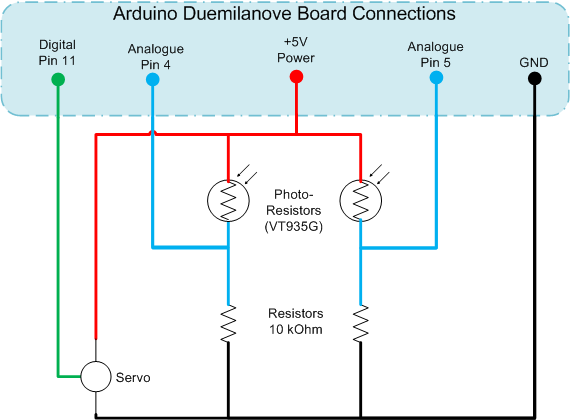
This project consists of two inputs which track light levels on the East/West which are then used to move a servo, rotating East/West tracking the strongest light level.
The crude prototype in all its glory......the surplus MSDN discs have found a use at last:

How It Works
The two light sensors are basic photoresistors, these are mounted at 90' to each other, imagine these are your eyes, if you look straight ahead at a wall, the left eye would point 45' to the left, and the right eye 45' to the right. These sensors are also shielded, so they will see the brightest light levels when pointing directly at the light source. If the light source then moves, a shadow is cast onto the sensor, changing its resistance.
When tracking the sunlight, e.g. for a solar panel, you would want the maximum sunlight intensity, to achieve this, both sensors would therefore need to see the same intensity of light. This is how we determine the input for the gap controller.
Read both of the input sensor values, and do a comparison, 0 difference means they are at the same light level, a -ve error value means the light is brighter to the right, and a +ve error value means the light is brighter to the left.
The servo is then sent up with a position value, and we simply increment or decrement the output on each scan to rotate the platform east and west to find the optimum balance light levels on the sensors again.
In the code, there are also upper and lower limits to prevent damage to the servo by driving hard against its end stops. A deadband value is also established in the code. This effectively means the output will not change, unless the error between the two inputs is greater than a certain value. The deadband prevents jitter and constant twitching of the sensor.
I have also added a very basic 2 point average to help smooth out spikes in the input sensors. In reality, you might want to filter this out further to filter out unwanted noise or spikes.
Using the Code
The sketch file provided in the download can be uploaded onto the Arduino. Let's take a look at the code in a bit more detail now.
The first part of the code is used to establish the IO Pin allocation, the variables for holding the input readings, the error and the rolling error average. The deadband range is also defined, as well as the upper and lower limits for the servo, and also the initial start point for the servo.
The #include statement makes reference to a prebuilt library for handling servo's on the Arduino. It basically allows a simple value to be written out to the servo object, and then takes care of the Pulse Width Modulation used to set the servo position.
#include <servo.h>
int pinL = 5; int pinR = 4; int pinServo = 11;
int leftValue = 0; int rightValue = 0; int error =0; int errorAVG = 0;
int deadband = 10; Servo hServo; int Position = 45;
int minPos = 5; int maxPos = 150;
float output = (maxPos - minPos) /2;
The next part of the code is the Arduino Setup method. This runs once and is effectively used to initialise anything you want before the main code loop executes. In this example, all I am doing is setting the Servo output to Min, Max and MidPoint for 5 Seconds each, to allow any positioning of the hardware on my desk for testing. The Serial statements just pump messages out the serial port and can be monitored on the PC.
void setup()
{
Serial.begin(9600);
hServo.attach(pinServo);
Serial.println("Moving Servo to Minimum Position");
hServo.write(minPos);
delay(5000);
Serial.println("Moving Servo to Maximum Position");
hServo.write(maxPos);
delay(5000);
Serial.println("Moving Servo to Mid-Point");
hServo.write(output);
delay(5000);
Serial.println("Going Live................");
}
The final part of the code is the main loop body, this is the loop that will run continuously until power is switched off or new code is downloaded to the Arduino.
The input values are first read, then some debug info is pumped out to the serial port. The error values are calculated, and the revised new position for the sensor is determined by adding the value returned by getTravel(). The limits are also checked to ensure we do not exceed these.
void loop()
{
leftValue = analogRead(pinL);
rightValue = analogRead(pinR);
Serial.print("L = "); Serial.print(leftValue); Serial.print(" | ");
Serial.print("R = "); Serial.print(rightValue); Serial.print(" | ");
Serial.print("E = "); Serial.print(error); Serial.print(" | ");
Serial.print("Eavg = "); Serial.print(errorAVG);
Serial.println();
error = leftValue - rightValue;
errorAVG = (errorAVG + error) / 2;
float newOutput = output + getTravel();
if (newOutput > maxPos)
{
Serial.println("At Upper Limit");
newOutput = maxPos;
}
else
{
if (newOutput < minPos)
{
Serial.println("At Lower Limit");
newOutput = minPos;
}
}
Serial.println("Writing output");
hServo.write(newOutput);
output = newOutput;
}
I also have a helper method getTravel() which is used to determine if I need to rotate left, rotate right or do nothing (e.g. within deadband) on each scan. It simply returns a +1, -1 or 0 which is then added to the current position before being written out to the servo.
int getTravel()
{
if (errorAVG < (deadband * -1))
{
return 1;
}
else
{
if (errorAVG > deadband)
{
return -1;
}
else
{
return 0;
}
}
}
The Working Prototype
A video of the prototype running can be found here.
Points of Interest
This is as simple as it gets. Ways that you could enhance this are:
- Implement an improved noise filtering on the input signals
- Add some form of PID (Proportional/Integral/Derivative) to the control algorithm
- Add a second servo and additional sensors for Vertical motion
What Else
Visit my other articles or my website for more Arduino bits and bobs. Search CodeProject for Arduino, there are also more by others.
History
- 22nd September 2010 - First version of article


 General
  News
News  Suggestion
  Question
  Bug
Bug  Answer
  Joke
Joke  Praise
  Rant
Rant  Admin
Admin 


