Article Series
Introduction
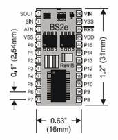
This is Part III of a series of articles whose goal is to introduce the reader to the world of embedded systems and their applications. In Robotics/Embedded Systems Part I, I covered the general idea of what embedded systems are. I gave examples of embedded system applications that can be found within your car today. I also briefly covered the different types of processor technologies that are available to you for your projects: General Purpose Processors, Single Purpose Processors and Application Specific Processors. In Robotics/Embedded Systems Part II, I covered a specific general-purpose processor made by Parallax. The BASIC Stamp II microprocessor family was covered in some length. I then picked the BASIC Stamp II e (BS2e) model and went over the memory architecture and some of the basic commands.
In Robotics/Embedded Systems Part III, I will actually be building the robot using the Basic Stamp II microcontroller. This article is more of an introduction to the basic concepts of a robot and how they can be practiced. So without further ado, I will begin Part III of the series.
Background
Understanding of computer architecture and microcontrollers is a plus for this series of articles. I will be discussing system design and theoretical concepts of microprocessors. Also, some basic electronics knowledge would be helpful once we get into circuit design for the robot.
Project Overview
I will be using BASIC Stamp II for building and programming some fundamental functionalities of a robot. The objective of this article series is to build the following four essential functionalities, i.e. logic and circuits within the robot.
- Sense the world around itself using the sensors.
- Make decisions based on what it senses.
- Control its motion based on the sensors and its decisions.
- Exchange information back to the user.
In the next section, I will discuss the assembly and testing of the hardware.
Assembling and Testing of the Robot
In order to successfully complete the project, the following hardware and software is needed for the design and implementation of the robot. The following table will list the hardware necessary.
Hardware component
| Quantity
|
BASIC Stamp 2 Microcontroller Module
| 1
|
Board of Education Rev C
| 1
|
1 KΩ Resistor
| 2
|
10 KΩ Resistor
| 2
|
2 KΩ Resistor
| 2
|
220 Ω Resistor
| 8
|
470 Ω Resistor
| 4
|
4.7 KΩ Resistor
| 2
|
0.01 µF Capacitor
| 2
|
0.1 µF Capacitor
| 2
|
Infrared LED
| 2
|
Red LED
| 2
|
Photo resistors (EG&G Vactec VT935G group B)
| 2
|
Infrared Receiver (Panasonic PNA4602M or equivalent)
| 2
|
LED Standoff for Infrared LED
| 2
|
LED Light Shield for Infrared LED
| 2
|
3-Pin Header
| 2
|
Whisker Wire
| 2
|
#4 Screw-Size Nylon Washer
| 2
|
7/8" 4-40 Pan-Head Screw, Phillips
| 2
|
½" Spacer, Aluminum, #4 round
| 2
|
Jumper Wires (bag of 10)
| 2
|
Piezo Speaker
| 1
|
Boe-Bot Hardware Pack
| 1
|
We also need to get the software to be able to program the BASIC Stamp II microcontroller, as well as a USB driver (if using USB) to be able to establish communication with the Board of Education Rev C. The following table lists the software components that are needed for this project.
Software component
|
BASIC Stamp Editor 2.0 or Higher
|
FTDI USB VCP Drivers
|
Connecting the Hardware
The first thing we need to do is place the BASIC Stamp II microcontroller into its proper place on the Board of Education. This can be achieved via the following steps:
- Set the 3-position switch on the Board of Education to position 0.
- Load batteries into the battery pack.
- Plug the BASIC Stamp II microcontroller into the Board of Education, inserting it into the socket as shown below:

NOTE: Make sure that the pins are lined up properly before pushing the microcontroller into the socket.
Before we continue on, we should test and make sure that we are able to communicate with the BASIC Stamp II microcontroller. If you have not yet installed BASIC Stamp Editorand FTDI USB VCP Driver, now is the time to do so. I will not cover installation of the software in this article; it should be straightforward. Run the BASIC Stamp Editor. Under the main menu, select Run->Identify… and a window should appear indicating if the hardware was detected or not.
If you are able to connect to the hardware successfully, you can test the microcontroller with a simple program. We will basically ask the microcontroller to send a message to the PC it is connected to. Here is the listing of the program used for testing the microcontroller:
DEBUG "Hello, this is Ed the robot!"
END
We need to transfer the program to the microcontroller. To do this, select Run -> Run from the main menu. Alternatively, you can press Ctrl+R as a keyboard shortcut. A download window will appear briefly as the program is being transmitted from the PC to the microcontroller. Once the program has been transmitted, you will see the test message, "Hello, this is Ed the Robot!" on the debug window.
Explaining of the Test Program
The first two lines of the code are called compiler directives and every PBASIC program will have them at the beginning. The first directive is called the Stamp Directive and it tells the Editor that you will be downloading the program to a BASIC Stamp II microcontroller. The second directive is called the PBASIC Directive and it tells the Editor that we are using version 2.5of the PBASIC programming language.
The DEBUG command tells the BASIC Stamp microcontroller to send a message to the PC using the serial cable. The END command, puts the BASIC Stamp into low power mode when it's done running the program. At this point, the microcontroller waits either for a reset button to be pressed or a new program to be loaded into the memory.
Assembly of the Robot
You can download the full manual from Parallax that gives detailed instructions on how to construct the robot. Here, I am going to cover the assembly of the robot in a shorter and faster way. That is, I will not get into too many details!
Mounting Servos to the Chassis
Mounting the Battery Pack
Mounting the Wheels
Attaching the Board to the Chassis
We need to test the servos after we have assembled the robot. This will help us make sure everything is working properly. To test the servos, we are going to use the following program, which will rotate the servos clockwise for 3 seconds and counterclockwise for 3 seconds.
DEBUG "Program Running!"
CounterVARWord
FOR counter = 1 to 122
PULSOUT 12, 650
PAUSE 20
NEXT
FOR counter = 1 to 40
PULSOUT 12, 750
PAUSE 20
NEXT
FOR counter = 1 to 122
PULSOUT 12, 850
PAUSE 20
NEXT
Controlling and Programming the Servos
Navigation is the main objective of any robotics project. The robot needs to be able to navigate in a given environment based on its sensors and the logic behind it. This is done through certain commands in the PBASIC language, which instruct the BASIC Stamp II microcontroller on how to control the direction, speed and duration of the servo motions.
The Parallax Continuous Rotation servos are the motors that will make the robot wheels turn. Controlling the servo motor's speed and direction involves a program that makes BASIC Stamp II send the message, over and over again. The message has to repeat itself around 50 times per second for the servo to maintain its speed and direction. Before moving forward, I will now describe some important commands that will be used for the purpose of controlling the servos. We will later discuss them in more detail.
The PAUSE command is used to tell the microcontroller to wait for a certain duration in milliseconds before executing the next command, i.e.: PAUSE 1000 will pause for 1 second. The DO and LOOP command is used to tell the microcontroller to repeat the commands in between the DO and LOOP code block until a condition is met, or forever, depending on the need of the application. For example, the following code will send a message every second.
DO
    DEBUG "Hello!", CR
    PAUSE 1000
LOOP
The HIGH and LOW command can be used to make BASIC Stamp alternate between Vdd and Vss. The pin argument is a number between 0 and 15 that indicates which I/O pin to connect to Vdd or Vss, i.e.: HIGH 0 will tell the microcontroller to set I/O pin 0 to Vdd. Similarly, LOW 0 will tell the microcontroller to set I/O pin 0 to Vss. The following figure illustrates the HIGH and LOW command:
DO
    HIGH 13
    PAUSE 1000
    LOW 13
LOOP
The code above will make the LED connected to pin 13 turn on and off every second.
Controlling the Servos
The high and low signals sent to BASIC Stamp II to send the servo motors must last for very precise amounts of time. This is because it is used by servos as instructions about where to turn. For this, we need more a precise command for controlling time duration.
The PULSOUT command can deliver high signals for precise amounts of time. Time is measured in units of two millionths of a second. For instance, you can send a signal to P13 (pin 13) that turns on the LED for 2µs, i.e.: PULSOUT 13, 1. PULSOUT 13, 65000 is the equivalent of running a high signal for 0.13 seconds. The following is a timing diagram for the high signal:
Connecting the Servos to the Board of Education
The first thing we need to do is connect the servos to the board. We will be using P13 and P12 of the microcontroller to send signals to the servos. The following schematic illustrates how this is done:
The next step is to actually center the servos. We need to write a program that sends the servos a signal, instructing them to stay still. The program for this signal will be a PULSOUT command and a PAUSE command inside a DO...LOOP. The following is a timing diagram for centering the servos:
From the timing diagram we can tell that for the PAUSE command we need a duration of 20ms, which is going to be PAUSE 20. For the 1.5ms we need to use the PULSOUT command such as: PULSOUT 12, 750. How to figure out the PULSOUT command's durations? 1.5 ms is 0.0015 s. Remember that whatever number is in the PULSOUT command's duration argument must be multiplied by 2 µs, i.e. 0.000002 s.
Duration argument = Pulse duration / 2 µs, i.e.: 0.0015s/0.000002s = 7500.
If the servo is already centered, it will not turn. If it is not centered, you will need to adjust the servo by slowly using the screw driver in the potentiometer access hole.
Testing the Servos
The Parallax Continuous Rotation servo turns full speed clockwise when you send it 1.3 ms pulses. Full speed ranges from 50 to 60 RPM.
The following program will perform what we need:
DEBUG "Program Running!"
DO
PULSOUT 13, 650
PAUSE 20
LOOP
A duration of 850 will send 1.7 ms pulses to the servo and will make the servo turn full speed counterclockwise.
DEBUG "Program Running!"
DO
PULSOUT 13, 850
PAUSE 20
LOOP
Controlling Servo Runtime
Here is an example of a FOR...NEXT loop that will make the servo turn for a few seconds:
FOR counter = 1 TO 100
    PULSOUT 13, 850
    PAUSE 20
NEXT
Each time through the loop, the PULSOUT command lasts for 1.7 ms. The PAUSE command lasts for 20 ms and it takes around 1.3 ms for the loop to execute. So, one time through the loop is = 1.7 ms + 20 ms + 1.3 ms = 23.0 ms. Since the loop executes 100 times, the time is 23 ms x 100 = 2.30 s.
With the basics in place, we can now start programming our robot to navigate in its surrounding environment. We can create the following subroutines that will help us coordinate the movement of the robot with the sensors. Here, I will list the four basic movements: Forward, Backward, Left and Right:
Forward:
FOR counter = 1 to 64
    PULSOUT 13, 850
    PULSOUT 12, 650
    PAUSE 20
NEXT
RETURN

Backward:
FOR counter = 1 to 64
    PULSOUT 13, 650
    PULSOUT 12, 850
    PAUSE 20
NEXT
RETURN

Left:
FOR counter = 1 to 24
    PULSOUT 13, 650
    PULSOUT 12, 650
    PAUSE 20
NEXT
RETURN

Right:
FOR counter = 1 to 24
    PULSOUT 13, 850
    PULSOUT 12, 850
    PAUSE 20
NEXT
RETURN
You can also build complex maneuvers, but I will not cover those in this article.
Giving the Robot Some Sense
Whiskers give the robot the ability to sense the world around it through touch, much like the antennae on an ant or the whiskers on a cat. The whiskers can also be combined with other sensors to make the robot more intelligent. First, we need to assemble the whiskers based on the schematic:
The final look and feel of the robot after we have attached the whiskers may be:
The next step is for us to program the BASIC Stamp II microcontroller to detect when a whisker is pressed. The I/O pins connected to each switch circuit monitor the voltage at the 10 kΩ pull-up resistor. When a given whisker is not pressed, the voltage at the I/O pin connected to that whisker is 5 V. When a whisker is pressed, the I/O line is shorted to ground (Vss), so the I/O line sees 0 V.
The following program is a test program that will report the state of the whiskers on the debug screen:
DEBUG "WHISKER STATE", CR,
    "LEFTRIGHT", CR,
    "========"

DO
    DEBUG CRSRXY, 0 , 3,
        "P5 = ", BIN IN5,
        "P7 = ", BIN IN7
    PAUSE 50
LOOP
Here you see two new commands, BIN and CRSRXY. The BIN command is a formatter that tells the Debug Terminal to display one binary digit, either 1 or 0. The CRSRXY command is a formatter that allows us to conveniently arrange information on the Debug Terminal. 0 and 3 indicate the column and row of the cursor on the terminal. I also attached an LED to the circuit. This way, we have a visual indicator of which whisker is being activated once the robot is not attached to the terminal. We will need to make the following addition to our circuit and also add a few extra lines of code to turn the LEDs on and off appropriately.
Add the following code to the program to make it work:
IF( IN7 = 0 ) THEN
    HIGH 1
ELSE
    LOW 1
ENDIF

IF( IN5 = 0 ) THEN
    HIGH 10
ELSE
    LOW 10
ENDIF
We can now write a program that will give the robot some intelligence when it collides with an object sensed by the whiskers. As soon as an object is detected, we would use the subroutines defined previously under the Navigation section of this article in order to perform the correct movement. I will outline the main section of the program here.
IF (IN5 = 0) AND (IN7 = 0) THEN
GOSUB Back_Up
GOSUB Turn_Left
GOSUB Turn_Left
ELSEIF (IN5 = 0) THEN
GOSUB Back_Up
GOSUB Turn_Right
ELSEIF (IN7 = 0) THEN
GOSUB Back_Up
GOSUB Turn_Left
ELSE
GOSUB Forward_Pulse
ENDIF
If both whiskers are pressed, a U-turn is executed. If the left whisker is pressed, then we will back up and make a right turn. If the right whisker is pressed, we will back up and make a left turn. The only thing this code does not cover is the occurrence of corners. For that, we need to write additional code.
The full source code for corner detection can be found in the following section. In brief, however: We have allocated two variables to store the old values of the whiskers. This will allow us to compare the whiskers to their previous values. If the robot then hits a wall four times in a short period, there is a counter that will call logic to back the robot up and make a 180 degree turn. It will then continue on its new path.
Source Listing for Whisker Navigation
DEBUG "Program Running!", CR
DEBUG "WHISKERSTATES", CR,
"LeftRight", CR,
"====== ======="
pulseCountVARByte
counterVARNib
old7VARBit
old5VARBit
FREQOUT 4, 2000, 3000
counter = 1
old7 = 0
old5 = 1
DO
DEBUG CRSRXY, 0, 3,
"P5 = ", BIN1 IN5,
"P7 = ", BIN1 IN7
PAUSE 50
IF( IN7 <> IN5 ) THEN
IF( old7 <> IN7 ) AND ( old5 <> IN5 ) THEN
counter = counter + 1
old7 = IN7
old5 = IN5
IF( counter > 4 ) THEN
counter = 1
GOSUB Back_up
GOSUB Turn_Left
GOSUB Turn_Left
ENDIF
ELSE
counter = 1
ENDIF
ENDIF
IF( IN5 = 0 ) AND ( IN7 = 0 ) THEN
HIGH 1
HIGH 10
GOSUB Back_Up
GOSUB Turn_Left
GOSUB Turn_Left
ELSEIF ( IN5 = 0 ) THEN
HIGH 10
GOSUB Back_Up
GOSUB Turn_Right
ELSEIF ( IN7 = 0 ) THEN
HIGH 1
GOSUB Back_Up
GOSUB Turn_Left
ELSE
LOW 10
LOW 1
GOSUB Forward_Pulse
ENDIF
LOOP
Navigation:
FOR counter = 1 TO pulseCount
PULSOUT 12, pulseRight
PULSOUT 13, pulseLeft
PAUSE 20
NEXT
PAUSE 200
RETURN
Forward_Pulse:
PULSOUT 12, 850
PULSOUT 13, 650
PAUSE 20
RETURN
Turn_Left:
FOR pulseCount = 0 TO 20
PULSOUT 12, 650
PULSOUT 13, 650
PAUSE 20
NEXT
RETURN
Turn_Right:
FOR pulseCount = 0 TO 20
PULSOUT 12, 850
PULSOUT 13, 850
PAUSE 20
NEXT
RETURN
Back_Up:
FOR pulseCount = 0 TO 40
PULSOUT 12, 650
PULSOUT 13, 850
PAUSE 20
NEXT
RETURN
END
Points of Interest
In this article, I have covered the assembly of the Parallax robot (Boe-Bot) and also gone over some of the microcontroller's basic programming. I have also discussed the input of simple sensors to make the robot aware of its surroundings. This has been accomplished via what is called Tactical Navigation with Whiskers. You can make the robot more intelligent about its surroundings using more advanced sensors such as photoresistors, infrared and distance detection sensors. I will cover these advanced sensors in Part IV of the article series. Once you assemble and set up your servos and get a handle of the navigation and logic of the robot, adding and modifying the sensors is a snap.
I hope you enjoyed Part III of the series and do send me your comments and feedback.
History
- 12 July, 2007 -- Original version posted


 General
  News
News  Suggestion
  Question
  Bug
Bug  Answer
  Joke
Joke  Praise
  Rant
Rant  Admin
Admin 


