Introduction
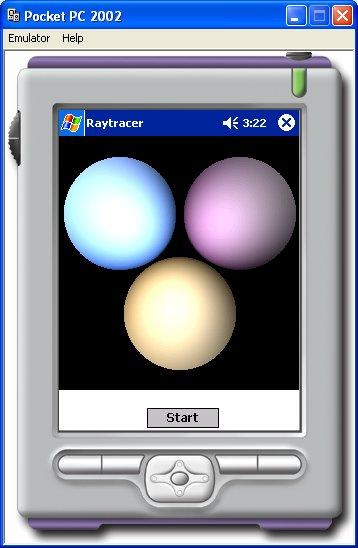
A raytracer is a program that attempts to display an object in three dimensions using a mathematical equivalent of the lit environment we experience in real life. It performs this by modelling the rays that emanate from a light source, and their interaction with the objects in the scene. This is a computationally expensive method, as it calculates the effect the light has on the material of the object for each pixel that is drawn, and can take a very long time to render(display a complete image), even on modern PCs. However, it is widely believed that raytracers are a very good way of introducing graphics theory, so I thought it would be fun to write a simple one that would work on the Compact Framework(CF). Mobile devices up to now have not been known for their graphical power, and the vast majority of them do not have a processor with a floating point unit, but considering the first raytracer I wrote was on a 8Mhz 68000 with 16 colours, the 200+MHz XScale processor with 16-bit graphics seems like a supercomputer:) Admittedly I haven't written one in between, being seduced by the dark side of OpenGL and Direct3D. Nevertheless, do not expect miracles. Even though this is a very simple raytracer implementation, it takes about 15-20 minutes to render the simple scene shown above on my (rather old) 200MHz iPaq.
Background
To understand how this code works, the principles behind 3d graphics and raytracing need to be explained. If you know any of this, feel free to skip ahead. This is probably going to be the quickest précis of basic graphics theory in history:)
3d Space
As programmers we are used to designing interfaces in 2D space, where x is the horizontal axis and y is the vertical axis. Obviously in 3D, a third axis is required which is at a right angle to the other two axes, in other words going into or out of the screen. This axis is referred to as the z axis. Projected onto a two dimensional screen:

When describing a point in 3D space the following form is used (x,y,z), so (3,4,5) would be 3 units along the x axis, 4 units along the y axis and 5 units along the z axis.
Vectors
A vector can be understood to be a line in 3D space, holding information about the line's direction, and the line's length. To be clear, the line between two points in 3d space, A and B can be calculated by subtracting the components of one from the other. It must also be understood that (A-B)!=(B-A). The vector (A-B)'s direction component points in the opposite direction to the vector (B-A)'s direction component.
A vector, confusingly, is represented in exactly the same way as a point in 3D space, (x,y,z). As they can be treated in a similar way for most mathematical operations, it simplifies the code involved, and points often use the same C#/C++ class, as they do here.
The length(magnitude) of a vector can be calculated by the following equation:
Where Vx, Vy and Vz are the parts of the vector. This is a very important operation, as the most useful vector is known as the unit vector, which is a vector with a length of 1. This is important for a number of reasons, not least of which is that it provides a unit of measurement along the direction of the vector. A vector is converted to a unit vector by a process known as normalisation, in which each of its components is divided by the magnitude if the vector.
The other important operator that acts upon a vector is known as the dot product. In simple terms, this provides information about the angle between any two vectors. In fact, the dot product provides the cosine of the angle. With two vectors V1 and V2, it is calculated thus:
where |Vn| denotes the magnitude of the vector.
There is a special case of vector, which is known as a normal. This is a vector which is used to describe a part of a surface, and is defined as being perpendicular to that part of the surface. Normals are very important when considering lighting, as lighting calculations are worked out relative to the angle between the light and the surface. Normals are usually normalised to simplify the calculations involving them.
Rays
A ray is a line in 3D space with a definite starting position. It is made up of two parts, its origin(R0) and its direction vector(Rd). These parts are used to calculate whether the ray intersects any objects in its path, by substituting the object's equation into the ray's line equation. The general equation of the ray is:
where t is the distance along the direction vector.
Sphere
The simplest interaction between a ray and any other object is the interaction with the sphere. Therefore the object that this raytracer is going to use is the sphere:) The sphere's equation is:
where (l,m,n) is the centre of the sphere and r is the sphere's radius. To find the intersection of the sphere and a ray the two equations have to be substituted into the quadratic form:
where the two quadratic roots would be the two intersection points with the sphere:
So, performing the substitution:
which can be solved using the quadratic equation:
and the normals of the intersection points can be calculated by subtracting them from the sphere's centre.
Lighting
This raytracer uses two forms of lighting, diffuse and specular.
Diffuse lighting is the amount of light reflected off a matt surface, where incoming light is reflected in all directions. The mathematical formula for diffuse lighting is:
where Kd is the diffuse colour of the surface material, N is the normalised surface normal and L is the normalised vector from the surface toward the light source, as can be seen below:
The smaller the angle between N and L, the larger the dot product between them, and so therefore the more light reflected by the surface.
Specular lighting is the amount of light reflected off a shiny surface, in what is known as the mirror direction. in other words, the light is reflected in a more concentrated way from the surface, and it depends on where the eye is as to whether and how much light is seen to be reflected:
The formula for specular lighting is as follows:
where Ks is the specular colour of the surface material, H is the normalised vector between L and V, which is the normalised vector pointing towards the eye. facing is 1 if N.L is more than 0, or 0 otherwise.
Using the code
The code is split up into several classes, many of which provide more functionality than is required by this application. the vector class contains a full floating point vector implementation, with overloaded operators for the arithmetic functions. It might be thought that a fixed point implementation would make more sense, but raytracers need precision. As with all of the code in this application, the vector implementation is not optimised, as it is meant more as a learning tool than anything else. If it were optimised, it would make more sense not to use operator overloading, as it tends to be quite slow under the CF. Likewise the colour class contains a floating point colour implementation. The displays on mobile devices tend to be 16-bit, but it is always a good idea to work with complete colour components (red, green, blue) when manipulating colours in the manner a graphics application does.
A ray is merely represented by a class containing an origin and a direction, plus some helper functions.
Objects, such as spheres, are inherited from the objbase class. This provides simple material and identification routines, as well as providing the prototype for the ray intersect function. The sphere class represent a sphere by its centre point and radius. It also provides the intersection routine explained above. This routine returns a structure containing all the information about the intersection:
public struct IntersectInfo
{
public bool hit;
public vector pos;
public colour col;
public vector normal;
}
Using the objbase class and the IntersectInfo structure, further objects, such as planes, cylinders, cones, etc, can be added.
Lighting is implemented by the lightmanager class, which as well as calculating the light interaction, also maintains the lights themselves. The lights are described by the following simple structure:
public struct light
{
public vector pos;
public colour col;
public light(light lgt)
{
pos=new vector(lgt.pos);
col=new colour(lgt.col);
}
public light(vector vec,colour clr)
{
pos=new vector(vec);
col=new colour(clr);
}
}
For each ray the lightmanager calculates the action of each light to get the colour at that point using the equations above by calling the getlitcolour function:
public colour getlitcolour(int lnum,vector pos,colour col,
vector normal,float shininess,vector eye)
{
colour litcol=new colour();
if(lnum>=m_pos)
return litcol;
vector N=normal-pos;
N=N.normalize();
float L=m_lights[lnum].pos.dotproduct(N);
if(L>0.0f)
litcol=col*m_lights[lnum].col*L;
vector Lv=(pos-m_lights[lnum].pos).normalize();
vector V=(eye-pos).normalize();
vector H=(Lv-V).normalize();
float specularweight=0.0f;
if(L>0.0f)
specularweight=(float)Math.Pow(Math.Max(
normal.dotproduct(H),0.0f),shininess);
colour specular=m_lights[lnum].col*specularweight;
litcol+=specular;
litcol.limit();
return litcol;
}
All of these are called by the raytrace class which calculates which rays are to be traced, and the precedence of the objects, so as to cause shadows on objects occluded by others.
The actual pixels are drawn on the screen using repeated calls to Graphics.FillRectangle, which, although slow, allows the raytraced image to be built up on the device's display, which is much more satisfying than watching a blank screen for 15 minutes, while it calculates the image. Also, as it goes along, it averages the colour being drawn with the last colour to perform some cheap anti-aliasing:)
The scene itself is hardcoded into the Form_Load function, and makes it quite clear how to change it:
light lgt=new light();
lgt.col=new colour(0.7f,0.7f,0.7f);
lgt.pos=new vector(100.0f,10.0f,-150.0f);
tracer.addlight(lgt);
sphere sph1=new sphere();
colour col=new colour(0.8f,0.7f,0.5f);
sph1.setup(new vector(0.0f,-50.0f,100.0f),40.0f);
sph1.ColourValue=col;
sph1.IdValue=1;
tracer.addobject(sph1);
sphere sph2=new sphere();
col=new colour(1.0f,0.7f,1.0f);
sph2.setup(new vector(60.0f,50.0f,100.0f),40.0f);
sph2.ColourValue=col;
sph2.IdValue=2;
tracer.addobject(sph2);
sphere sph3=new sphere();
col=new colour(0.5f,0.7f,1.0f);
sph3.setup(new vector(-60.0f,50.0f,100.0f),40.0f);
sph3.ColourValue=col;
sph3.IdValue=3;
tracer.addobject(sph3);
where tracer is the raytrace class. As can be seen, it wouldn't take very much to allow the application to load the scene information from a data file.
Points of Interest
This was an interesting application to code, as I am used to coding in native C++, and have only dipped my feet into C# for small utilities in the past (as I'm sure is obvious from the code:), so from that point of view, this was a learning experience for me. However, the way in which I wrote the code was designed so that it would be a learning experience for those with no graphics background. The Compact Framework may not seem to have been much help in the design of this project, but anyone who knows the mountains of pointer arithmetic and memory leak fixing usually involved in graphics programming can see the benefit of a garbage collected environment on any device, as long as its use is not to the detriment of the speed of the application.
History


 General
  News
News  Suggestion
  Question
  Bug
Bug  Answer
  Joke
Joke  Praise
  Rant
Rant  Admin
Admin 


