D-FOM Analysis of Microcontroller System (MCU) --
-- a case study to develop confidence in the approach:
A Microcontroller may be defined as an application specific schematic combination of ALU, Memory (RAM/ROM), Data buses and Address buses, I/O ports (Serial/Parallel), and Controls. In fact, Microcontroller is a combination of a microprocessor with I/O ports on a single chip.
In my paper "D-FOM: Yet another OOM", I proposed an Object Oriented Model (OOM) that is supposed to be advantageous in designing and VHDL modeling of such chips. Here, I have taken Designing and VHDL Modeling of a Microcontroller System with D-FOM approach as a case study to develop confidence in the approach. Before that, let's recall the concept of D-FOM.
Components of D-FOM:
- Actor: Something that uses the system.
- Use Case: Tells how the system is used.
- Unified Actor: Actor inside the system.
- Unified Use Case: Use case for unified Actor.
- Functional Actor: An actor or unified actor.
- Functional Use Case: A use case or unified use case.
Steps in D-FOM:
- First step towards analysis:
- Find Actors
- Find Use Cases
- Find Unified Actors
- Find Unified Use Cases
- FUCA
- Prepare FUCM
- Iterate FUCM
- Where to end analysis: A rough idea for beginners.
- When you get no further module inside.
- Experience may make an earlier end too.
- Moving forward towards design: Implementation View (Involve Dependencies)
- One level of tree at a time and integrate for one level up on the path (Bottom-Up)
- Unified Actors->Class
- Functional Use Case->Method
- Iterate and get generalization
- Get Packages for similar classes
- Sequence Analysis and Sequence Diagrams
- Bottom-Up Strategy: Sequence analysis for leaves (statements)->Sequence analysis of one level up (functions)->Sequence analysis for system (Process)
- Implementation:
- Code for leaf-sequence diagram and make functions
- Integrate functions to get one level up in the tree
- Integrate to get the system-code
- Deployment Analysis according to the problem in hand as per traditional approach (not really tough because of new systems, networking technologies, and database concepts).
Summarized list of Advantages:
- Dependent Class identification reduces confusions.
- New joining member is expected to start working quickly because he/she needs to study and understand FUCM only.
- Concentrated error prone area.
- Approach gives a design equally suitable to be implemented in OOPL and HDL. So is applicable to HDL also.
- Parallel designing of H/W and its simulator made possible.
- Automation made possible.
- Reduced Effort and Resource consumption is expected.
Summarized list of limitations:
- Need a proper FUCA. FUCM needs to be made with in depth knowledge of the system.
- Over dependent on FUCM.
- Is not globally acceptable but depends on nature of problem. May not be good for highly complex architectures. (Complexity means to interdependencies of modules, which may create huge integration problems. But the same is the case in traditional approaches too, so nothing exceptional here.)
- Experience in the field of the project gives better results.
First Stage Analysis of MCU
In the first stage analysis, the Micro-controller system has been divided into four major parts:
- Decoder
- Control Unit
- Arithmetic Logic Unit
- Memory - RAM + ROM
There may not be a big requirement to go in details of these right now. Just by this much knowledge, we can proceed for now, and later we will explore the details to design for the system-modules and the system. If we see into the functionality of the system, we can summarize it as follows:
Decoder: decodes the input signal to an instruction bit pattern.
This decoder is not the simple ordinary decoder that takes a single line input and provides selective multiple line output. Rather, it is a complex unit in Micro-controller system that has complete information about the instruction set of Micro-controller. This unit takes an input binary word and gathers all information about this word like, if it is a valid command or not, if it is an instruction from the instruction set of the system, how many data values does it need to be executed? It indicates whether the command operates on one/two/three or no operand, how many other (Next) bytes are to be read for complete instruction, and required data information for its execution etc. Finally, all this information is sent to control unit for appropriate action and functioning for the system.
Control Unit: Controls the Signal and Data flow through the components
The control unit is the heart of any Microprocessor or Microcontroller system. As in a human body, the heart takes the responsibility of circulating the blood in the whole body through nerve web; in the same way, in a Microcontroller, the Control Unit is responsible for circulating the control and data signals throughout the system through buses. The brief functioning of control unit may be summarized as:
The control unit takes the direct input command signal from the command generator and processes it to the decoder. The Decoder converts this signal to an Op-Code and gives it to the control unit with different other information as discussed above. Control unit checks if it is some control-operation or arithmetic/logic operation. Arithmetic/Logic op-code is sent to ALU for operation. Control unit sends a Rd/Wr signal to the memory unit. For the response of a Rd signal, the memory allows Control unit to read a required location, and for Wr signal, some information may be entered in it (Memory access). It reads the data from memory and sends it to ALU where it is operated on. Control unit receives results from ALU which is then stored in memory with a Wr signal. It executes all control and data-transfer operations for the system.
So, the Control unit actually controls the flow of data and control signals in the system.
Arithmetic Logic Unit: Covers all Logical and Mathematical Calculations
This is responsible for all Arithmetic and Logic operations required for the system functioning.
Arithmetic Operations: ADD, ADDC, SUBB, INC, DEC, MUL, DIV.
Logic Operations: ANL (AND), ORL (OR), XRL (XOR), CLR, CPL, RL, RC, RR, RRC, SWAP.
Memory: store information for future use
Memory is the device to store the control and data information about (and for) the system. It is a collection of flip-flops that may be addressed with a number of select-lines called address-bus of the chip. A list of functionalities:
- Checks for Rd/Wr signal
- For a Rd signal, it stores the information on its data-bus on a location indicated by its address-bus status.
- For a Wr signal, it puts the same information (binary signal) on its data-bus as is on the location specified by its address bus.
Table-1 shows the Functional Usecase Analysis of the MCU System (FUCM). Figure-1 shows the Functional Use Case Model for Microcontroller, following which Figure-2 shows D-FOM Class Diagram for it. These analysis and diagrams show the first stage analysis of the system, means contribute to the first iteration of the system design. But this analysis is not directly implementable at this stage. As told earlier, the analysis phase goes top-down way. When we reach an adequate level of abstraction where we are able to implement our design, we start implementation in bottom-up way, taking one level at a time. This first iteration analysis then contributes to integration of the system using its components viz. decoder, ALU, control unit, and memory. The first iteration FUCM then contributes to analyze and implement how different components interact with each other. Not only this, but also this system level FUCA gives an idea of next level FUCA for different components individually as we see while preparing a FUCM for decoder unit later in this example.
| Functional Actor | Type | Functional Use Cases |
|---|
| Command Generator | Actor |
|
| Control Unit (CTR) | Unified Actor |
- Get_Command
- Respond
- Get Opcode
- Get_Rd/Wr_Signal
- Write in memory
- Read memory
- Get Result
- Reset Signal
|
| Memory | Unified Actor |
- Get_Rd/Wr_Signal
- Write in
- Read
- Reset Signal
|
| Decoder | Unified Actor |
- Respond to command
- Get Opcode
|
| Reset (RST) | Actor |
- Reset System: Reset Signal is generated to reset & restart the Control Unit, ALU & Memory functions.
|
Table 1: Functional Use Case Analysis of MCU.
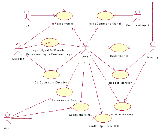
Figure 1: FUCM for Microcontroller System.

Figure 2: D-FOM Class Model for Microcontroller System.
(Click on the picture to see enlarged view)
So, this is what we need for our first iteration for analysis of Microcontroller systems. In the next iterations, we will elaborate the subsystems and modules of the same using D-FOM, and will try to go till statement-level where we can implement the system with either OOPS or VHDL as we need without major changes in design. We can see here that, as I specified in my notes, D-FOM works efficiently in a Top-Down manner for a system. Here also, we have started from a top-level abstraction and will move to bottom to statement level.
I will complete implementation of one module with D-FOM to describe the complete process of implementation. Let's take the ‘Decoder’ module for implementation in VHSIC Hardware Description Language (VHDL).
Decoder takes an input from the control unit that is some 8-bit combination of ‘0’ and ‘1’. This unit has the information of structure of all the commands that the system recognizes. As once the control unit gives some 8-bit input to the unit, decoder analyzes as if the input is some valid command for the system or not. If this is not a valid command, the decoder alerts the control unit to give some error code, or alerts the system not to respond for this input. But if the command is a valid one, the decoder looks for its structure and tells the control unit about that.
Here the structure of the command includes the following:
- What the command is: The decoder tells the control unit the op-code for the input. Decoder tells nothing about the implementation or the operation of the command. It only returns the op-code and not its functionality.
- How many data bytes needed: The decoder tells the control unit about how many data bytes are required for executing the command and updating the system with the output results. Here again, the decoder tells nothing about how the results are to be calculated or how the system is updated, but only the number of bytes of the data for op-code is told to the control unit. In 8051-specification, a command may need either ‘0’ or ‘1’, a maximum of ‘2’ bytes of data.
Figure-1 shows FUCM for the internal decoder of Microcontroller system as per its specifications, and following Figure-2 shows corresponding D-FOM class analysis of this command decoder of MCU.
Figure 1: Functional Use Case Model for Internal Decoder of MCU System.
It can be noticed here that the above use case analysis is almost a subset of the system level FUCA. From the system level FUCA; we have just pulled out the decoder-FA and its associated FU Cases. Finally, we may add some more use cases or the actors as if required on the basis of our iterations in the analysis process. Here, we have a single functional actor, decoder. Let’s get the class diagram, which will be having only one class Decoder and hence no associations.
Figure 2: D-FOM Class Model for Internal Decoder of MCU System.
Now the functions need to be analyzed in terms of the sequence diagrams. For taking the input, the unit does nothing of efforts but just accepts an input and does not modify it. For this, we may not need to have a special function implementation. So, we may ignore the functional implementation of the method input().
Now, we can make the sequence diagram for each implemental method, if required, to describe its algorithmic sequence of signals. In the in hand case, we can prepare a skeleton in VHDL, using this analysis as follows:
(Note: terms in square-brackets [ ] shown to be replaced by coder team with appropriate values.)
entity decoder is
port (Input: in UNSIGNED(7 downto 0); rst: in bit;
cmd_opcode:out bit_vector(6 downto 0);
cmd_length: out bit_vector(1 downto 0));
end decoder;
architecture behavioral of decoder is
function opcode_out(I:UNSIGNED) return bit_vector is
variable opcode:bit_vector(6 downto 0);
begin
if Input=[input_bit_ pattern1] then opcode:=[opcode1]; elsif
Input=[input_bit_ pattern2] then opcode:=[opcode2]; elsif
Input=[input_bit_ pattern3] then opcode:=[opcode3]; elsif
- - - - - -
- - - - - -
- - - - - -
- - - - - -
- - - - - -
- - - - - -
end if;
return opcode;
end opcode_out;
function bytelength_out (I:UNSIGNED) return bit_vector is
variable length:bit_vector(1 downto 0);
begin
--"00" means single byte command…
--"01" means two byte command…
--"11" means three byte command…
if Input=[input_bit_ pattern1] then length:=[length-code1]; elsif
Input=[input_bit_ pattern2] then length:=[length-code2]; elsif
Input=[input_bit_ pattern3] then length:=[length-code3]; elsif
- - - - - -
- - - - - -
- - - - - -
- - - - - -
- - - - - -
end if;
return length;
end bytelength_out;
procedure reset(opout:out bit_vector(6 downto 0);
oplength:out bit_vector(1 downto 0)) is
begin
opout:="reset_opcode";
oplength:="00";
end reset;
begin --[architecture begins here]
process(input,rst)
variable opcode:bit_vector(6 downto 0);
variable length:bit_vector(1 downto 0);
begin
if rst=
reset(opcode,length);
cmd_opcode<=opcode;
cmd_length<=length;
else
cmd_opcode<=opcode_out(Input);
cmd_length<=bytelength_out(Input);
end if;
end process;
end behavioral;
Now, finally this skeleton-code may be customized as per requirement by the coder team. The final code as we coded comes as follows:
library IEEE;
use IEEE.STD_LOGIC_1164.ALL;
use IEEE.STD_LOGIC_ARITH.ALL;
use IEEE.STD_LOGIC_UNSIGNED.ALL;
use WORK.definition.all;
-- Uncomment the following lines to use the declarations that are
-- provided for instantiating Xilinx primitive components.
-- library UNISIM;
-- use UNISIM.VComponents.all;
entity decoder is
port (Input: in UNSIGNED(7 downto 0);
rst: in std_logic;
cmd_opcode:out std_logic_vector(6 downto 0);
cmd_length: out std_logic_vector(1 downto 0));
end decoder;
Architecture behavioral of decoder is
function opcode_out(I:UNSIGNED) return std_logic_vector is
variable opcode:std_logic_vector(6 downto 0);
begin
if I(4 downto 0) = ACALL then opcode:=("0000000"); elsif
I(7 downto 3) = ADD_1 then opcode:= ("0000001"); elsif
I(7 downto 0) = ADD_2 then opcode:= ("0000010"); elsif
I(7 downto 1) = ADD_3 then opcode:= ("0000011"); elsif
I(7 downto 0) = ADD_4 then opcode:= ("0000100"); elsif
I(7 downto 3) = ADDC_1 then opcode:= ("0000101"); elsif
I(7 downto 0) = ADDC_2 then opcode:= ("0000110"); elsif
I(7 downto 1) = ADDC_3 then opcode:= ("0000111"); elsif
I(7 downto 0) = ADDC_4 then opcode:= ("0001000"); elsif
I(4 downto 0) = AJMP then opcode:= ("0001001"); elsif
I(7 downto 3) = ANL_1 then opcode:= ("0001010"); elsif
I(7 downto 0) = ANL_2 then opcode:= ("0001011"); elsif
I(7 downto 1) = ANL_3 then opcode:= ("0001100"); elsif
I(7 downto 0) = ANL_4 then opcode:= ("0001101"); elsif
I(7 downto 0) = ANL_5 then opcode:= ("0001110"); elsif
I(7 downto 0) = ANL_6 then opcode:= ("0001111"); elsif
I(7 downto 0) = ANL_7 then opcode:= ("0010000"); elsif
I(7 downto 0) = ANL_8 then opcode:= ("0010001"); elsif
I(7 downto 0) = CJNE_1 then opcode:= ("0010010"); elsif
I(7 downto 0) = CJNE_2 then opcode:= ("0010011"); elsif
I(7 downto 3) = CJNE_3 then opcode:= ("0010100"); elsif
I(7 downto 1) = CJNE_4 then opcode:= ("0010101"); elsif
I(7 downto 0) = CLR_1 then opcode:= ("0010110"); elsif
I(7 downto 0) = CLR_2 then opcode:= ("0010111"); elsif
I(7 downto 0) = CLR_3 then opcode:= ("0011000"); elsif
I(7 downto 0) = CPL_1 then opcode:= ("0011001"); elsif
I(7 downto 0) = CPL_2 then opcode:= ("0011010"); elsif
I(7 downto 0) = CPL_3 then opcode:= ("0011011"); elsif
I(7 downto 0) = DA then opcode:= ("0011100"); elsif
I(7 downto 0) = DEC_1 then opcode:= ("0011101"); elsif
I(7 downto 3) = DEC_2 then opcode:= ("0011110"); elsif
I(7 downto 0) = DEC_3 then opcode:= ("0011111"); elsif
I(7 downto 1) = DEC_4 then opcode:= ("0100000"); elsif
I(7 downto 0) = DIV then opcode:= ("0100001"); elsif
I(7 downto 3) = DJNZ_1 then opcode:= ("0100010"); elsif
I(7 downto 0) = DJNZ_2 then opcode:= ("0100011"); elsif
I(7 downto 0) = INC_1 then opcode:= ("0100100"); elsif
I(7 downto 3) = INC_2 then opcode:= ("0100101"); elsif
I(7 downto 0) = INC_3 then opcode:= ("0100110"); elsif
I(7 downto 1) = INC_4 then opcode:= ("0100111"); elsif
I(7 downto 0) = INC_5 then opcode:= ("0101000"); elsif
I(7 downto 0) = JB then opcode:= ("0101001"); elsif
I(7 downto 0) = JBC then opcode:= ("0101010"); elsif
I(7 downto 0) = JC then opcode:= ("0101011"); elsif
I(7 downto 0) = JMP then opcode:= ("0101100"); elsif
I(7 downto 0) = JNB then opcode:= ("0101101"); elsif
I(7 downto 0) = JNC then opcode:= ("0101110"); elsif
I(7 downto 0) = JNZ then opcode:= ("0101111"); elsif
I(7 downto 0) = JZ then opcode:= ("0110000"); elsif
I(7 downto 0) = LCALL then opcode:= ("0110001"); elsif
I(7 downto 0) = LJMP then opcode:= ("0110010"); elsif
I(7 downto 3) = MOV_1 then opcode:= ("0110011"); elsif
I(7 downto 0) = MOV_2 then opcode:= ("0110100"); elsif
I(7 downto 1) = MOV_3 then opcode:= ("0110101"); elsif
I(7 downto 0) = MOV_4 then opcode:= ("0110110"); elsif
I(7 downto 3) = MOV_5 then opcode:= ("0110111"); elsif
I(7 downto 3) = MOV_6 then opcode:= ("0111000"); elsif
I(7 downto 3) = MOV_7 then opcode:= ("0111001"); elsif
I(7 downto 0) = MOV_8 then opcode:= ("0111010"); elsif
I(7 downto 3) = MOV_9 then opcode:= ("0111011"); elsif
I(7 downto 0) = MOV_10 then opcode:= ("0111100"); elsif
I(7 downto 1) = MOV_11 then opcode:= ("0111101"); elsif
I(7 downto 0) = MOV_12 then opcode:= ("0111110"); elsif
I(7 downto 1) = MOV_13 then opcode:= ("0111111"); elsif
I(7 downto 1) = MOV_14 then opcode:= ("1000000"); elsif
I(7 downto 1) = MOV_15 then opcode:= ("1000001"); elsif
I(7 downto 0) = MOV_16 then opcode:= ("1000010"); elsif
I(7 downto 0) = MOV_17 then opcode:= ("1000011"); elsif
I(7 downto 0) = MOV_18 then opcode:= ("1000100"); elsif
I(7 downto 0) = MOVC_1 then opcode:= ("1000101"); elsif
I(7 downto 0) = MOVC_2 then opcode:= ("1000110"); elsif
I(7 downto 1) = MOVX_1 then opcode:= ("1000111"); elsif
I(7 downto 0) = MOVX_2 then opcode:= ("1001000"); elsif
I(7 downto 1) = MOVX_3 then opcode:= ("1001001"); elsif
I(7 downto 0) = MOVX_4 then opcode:= ("1001010"); elsif
I(7 downto 0) = MUL then opcode:= ("1001011"); elsif
I(7 downto 0) = NOP then opcode:= ("1001100"); elsif
I(7 downto 3) = ORL_1 then opcode:= ("1001101"); elsif
I(7 downto 0) = ORL_2 then opcode:= ("1001110"); elsif
I(7 downto 1) = ORL_3 then opcode:= ("1001111"); elsif
I(7 downto 0) = ORL_4 then opcode:= ("1010000"); elsif
I(7 downto 0) = ORL_5 then opcode:= ("1010001"); elsif
I(7 downto 0) = ORL_6 then opcode:= ("1010010"); elsif
I(7 downto 0) = ORL_7 then opcode:= ("1010011"); elsif
I(7 downto 0) = ORL_8 then opcode:= ("1010100"); elsif
I(7 downto 0) = POP then opcode:= ("1010101"); elsif
I(7 downto 0) = PUSH then opcode:= ("1010110"); elsif
I(7 downto 0) = RET then opcode:= ("1010111"); elsif
I(7 downto 0) = RETI then opcode:= ("1011000"); elsif
I(7 downto 0) = RL then opcode:= ("1011001"); elsif
I(7 downto 0) = RLC then opcode:= ("1011010"); elsif
I(7 downto 0) = RR then opcode:= ("1011011"); elsif
I(7 downto 0) = RRC then opcode:= ("1011100"); elsif
I(7 downto 0) = SETB_1 then opcode:= ("1011101"); elsif
I(7 downto 0) = SETB_2 then opcode:= ("1011110"); elsif
I(7 downto 0) = SJMP then opcode:= ("1011111"); elsif
I(7 downto 3) = SUBB_1 then opcode:= ("1100000"); elsif
I(7 downto 0) = SUBB_2 then opcode:= ("1100001"); elsif
I(7 downto 1) = SUBB_3 then opcode:= ("1100010"); elsif
I(7 downto 0) = SUBB_4 then opcode:= ("1100011"); elsif
I(7 downto 0) = SWAP then opcode:= ("1100100"); elsif
I(7 downto 3) = XCH_1 then opcode:= ("1100101"); elsif
I(7 downto 0) = XCH_2 then opcode:= ("1100110"); elsif
I(7 downto 1) = XCH_3 then opcode:= ("1100111"); elsif
I(7 downto 1) = XCHD then opcode:= ("1101000"); elsif
I(7 downto 3) = XRL_1 then opcode:= ("1101001"); elsif
I(7 downto 0) = XRL_2 then opcode:= ("1101010"); elsif
I(7 downto 1) = XRL_3 then opcode:= ("1101011"); elsif
I(7 downto 0) = XRL_4 then opcode:= ("1101100"); elsif
I(7 downto 0) = XRL_5 then opcode:= ("1101101"); elsif
I(7 downto 0) = XRL_6 then opcode:= ("1101110"); else
opcode:= ("1101111");
end if;
return opcode;
end opcode_out;
function bytelength_out (I:UNSIGNED) return std_logic_vector is
variable length:std_logic_vector(1 downto 0);
begin
-- "00" means single byte command… No more bytes need to be read.
-- "01" means two byte command… One more byte needs to be read.
-- "11" means three byte command… Two more bytes need to be read.
if I(4 downto 0) = ACALL then length:=("01"); elsif
I(7 downto 3) = ADD_1 then length:=("00"); elsif
I(7 downto 0) = ADD_2 then length:=("01"); elsif
I(7 downto 1) = ADD_3 then length:=("00"); elsif
I(7 downto 0) = ADD_4 then length:=("01"); elsif
I(7 downto 3) = ADDC_1 then length:=("00"); elsif
I(7 downto 0) = ADDC_2 then length:=("01"); elsif
I(7 downto 1) = ADDC_3 then length:=("00"); elsif
I(7 downto 0) = ADDC_4 then length:=("01"); elsif
I(4 downto 0) = AJMP then length:=("01"); elsif
I(7 downto 3) = ANL_1 then length:=("00"); elsif
I(7 downto 0) = ANL_2 then length:=("01"); elsif
I(7 downto 1) = ANL_3 then length:=("00"); elsif
I(7 downto 0) = ANL_4 then length:=("01"); elsif
I(7 downto 0) = ANL_5 then length:=("01"); elsif
I(7 downto 0) = ANL_6 then length:=("11"); elsif
I(7 downto 0) = ANL_7 then length:=("01"); elsif
I(7 downto 0) = ANL_8 then length:=("01"); elsif
I(7 downto 0) = CJNE_1 then length:=("11"); elsif
I(7 downto 0) = CJNE_2 then length:=("11"); elsif
I(7 downto 3) = CJNE_3 then length:=("11"); elsif
I(7 downto 1) = CJNE_4 then length:=("11"); elsif
I(7 downto 0) = CLR_1 then length:=("00"); elsif
I(7 downto 0) = CLR_2 then length:=("00"); elsif
I(7 downto 0) = CLR_3 then length:=("01"); elsif
I(7 downto 0) = CPL_1 then length:=("00"); elsif
I(7 downto 0) = CPL_2 then length:=("00"); elsif
I(7 downto 0) = CPL_3 then length:=("01"); elsif
I(7 downto 0) = DA then length:=("00"); elsif
I(7 downto 0) = DEC_1 then length:=("00"); elsif
I(7 downto 3) = DEC_2 then length:=("00"); elsif
I(7 downto 0) = DEC_3 then length:=("01"); elsif
I(7 downto 1) = DEC_4 then length:=("00"); elsif
I(7 downto 0) = DIV then length:=("00"); elsif
I(7 downto 3) = DJNZ_1 then length:=("01"); elsif
I(7 downto 0) = DJNZ_2 then length:=("11"); elsif
I(7 downto 0) = INC_1 then length:=("00"); elsif
I(7 downto 3) = INC_2 then length:=("00"); elsif
I(7 downto 0) = INC_3 then length:=("01"); elsif
I(7 downto 1) = INC_4 then length:=("00"); elsif
I(7 downto 0) = INC_5 then length:=("00"); elsif
I(7 downto 0) = JB then length:=("11"); elsif
I(7 downto 0) = JBC then length:=("11"); elsif
I(7 downto 0) = JC then length:=("01"); elsif
I(7 downto 0) = JMP then length:=("00"); elsif
I(7 downto 0) = JNB then length:=("11"); elsif
I(7 downto 0) = JNC then length:=("01"); elsif
I(7 downto 0) = JNZ then length:=("01"); elsif
I(7 downto 0) = JZ then length:=("01"); elsif
I(7 downto 0) = LCALL then length:=("11"); elsif
I(7 downto 0) = LJMP then length:=("11"); elsif
I(7 downto 3) = MOV_1 then length:=("00"); elsif
I(7 downto 0) = MOV_2 then length:=("01"); elsif
I(7 downto 1) = MOV_3 then length:=("00"); elsif
I(7 downto 0) = MOV_4 then length:=("01"); elsif
I(7 downto 3) = MOV_5 then length:=("00"); elsif
I(7 downto 3) = MOV_6 then length:=("01"); elsif
I(7 downto 3) = MOV_7 then length:=("01"); elsif
I(7 downto 0) = MOV_8 then length:=("01"); elsif
I(7 downto 3) = MOV_9 then length:=("01"); elsif
I(7 downto 0) = MOV_10 then length:=("11"); elsif
I(7 downto 1) = MOV_11 then length:=("01"); elsif
I(7 downto 0) = MOV_12 then length:=("11"); elsif
I(7 downto 1) = MOV_13 then length:=("00"); elsif
I(7 downto 1) = MOV_14 then length:=("01"); elsif
I(7 downto 1) = MOV_15 then length:=("01"); elsif
I(7 downto 0) = MOV_16 then length:=("01"); elsif
I(7 downto 0) = MOV_17 then length:=("01"); elsif
I(7 downto 0) = MOV_18 then length:=("11"); elsif
I(7 downto 0) = MOVC_1 then length:=("00"); elsif
I(7 downto 0) = MOVC_2 then length:=("00"); elsif
I(7 downto 1) = MOVX_1 then length:=("00"); elsif
I(7 downto 0) = MOVX_2 then length:=("00"); elsif
I(7 downto 1) = MOVX_3 then length:=("00"); elsif
I(7 downto 0) = MOVX_4 then length:=("00"); elsif
I(7 downto 0) = MUL then length:=("00"); elsif
I(7 downto 0) = NOP then length:=("00"); elsif
I(7 downto 3) = ORL_1 then length:=("00"); elsif
I(7 downto 0) = ORL_2 then length:=("01"); elsif
I(7 downto 1) = ORL_3 then length:=("00"); elsif
I(7 downto 0) = ORL_4 then length:=("01"); elsif
I(7 downto 0) = ORL_5 then length:=("01"); elsif
I(7 downto 0) = ORL_6 then length:=("11"); elsif
I(7 downto 0) = ORL_7 then length:=("01"); elsif
I(7 downto 0) = ORL_8 then length:=("01"); elsif
I(7 downto 0) = POP then length:=("01"); elsif
I(7 downto 0) = PUSH then length:=("01"); elsif
I(7 downto 0) = RET then length:=("00"); elsif
I(7 downto 0) = RETI then length:=("00"); elsif
I(7 downto 0) = RL then length:=("00"); elsif
I(7 downto 0) = RLC then length:=("00"); elsif
I(7 downto 0) = RR then length:=("00"); elsif
I(7 downto 0) = RRC then length:=("00"); elsif
I(7 downto 0) = SETB_1 then length:=("00"); elsif
I(7 downto 0) = SETB_2 then length:=("01"); elsif
I(7 downto 0) = SJMP then length:=("01"); elsif
I(7 downto 3) = SUBB_1 then length:=("00"); elsif
I(7 downto 0) = SUBB_2 then length:=("01"); elsif
I(7 downto 1) = SUBB_3 then length:=("00"); elsif
I(7 downto 0) = SUBB_4 then length:=("01"); elsif
I(7 downto 0) = SWAP then length:=("00"); elsif
I(7 downto 3) = XCH_1 then length:=("00"); elsif
I(7 downto 0) = XCH_2 then length:=("01"); elsif
I(7 downto 1) = XCH_3 then length:=("00"); elsif
I(7 downto 1) = XCHD then length:=("00"); elsif
I(7 downto 3) = XRL_1 then length:=("00"); elsif
I(7 downto 0) = XRL_2 then length:=("01"); elsif
I(7 downto 1) = XRL_3 then length:=("00"); elsif
I(7 downto 0) = XRL_4 then length:=("01"); elsif
I(7 downto 0) = XRL_5 then length:=("01"); elsif
I(7 downto 0) = XRL_6 then length:=("11"); else
length:=("00");
end if;
return length;
end bytelength_out;
Procedure reset(opout:out std_logic_vector(6 downto 0);
oplength:out std_logic_vector(1 downto 0)) is
begin
opout:="1101111";
oplength:="00";
end reset;
--Architecture begins here
begin
process(input,rst)
variable opcode:std_logic_vector(6 downto 0);
variable length:std_logic_vector(1 downto 0);
begin
if rst=
reset(opcode,length);
cmd_opcode(6 downto 0)<=opcode;
cmd_length<=length;
else
cmd_opcode(6 downto 0)<=opcode_out(Input);
cmd_length<=bytelength_out(Input);
end if;
end process;
end behavioral;
Proceeding Works
In the later proceedings, I will be implementing the other components of the Microcontroller system viz. Memory including internal RAM and ROM, and ALU, and finally, the integrated VHDL Model of the system will be demonstrated.
Reference:
- Terry Quatrani, Visual Modeling with Rational Rose 2000 and UML, Addison Wesley.
- James Rumbaugh, Object Oriented Analysis and Design, Prentice Hall, 2002.
- Martin Fowler, What’s a Model for?
- Martin Fowler, Who needs an Architect? IEEE Software July/August 2003.
- Michael A. Ogush, Derek Coleman, Dorothea Beringer, A Template for Documenting Software and Firmware Architectures (Version 1.3, 15-Mar-00).
- Rational Software, Unified Modeling Language, version 1.1, 1998.


 General
  News
News  Suggestion
  Question
  Bug
Bug  Answer
  Joke
Joke  Praise
  Rant
Rant  Admin
Admin 


 sir pls tell me ab8 the links for full version of xilinx n all sofwares for development thanks
  You can tell me your E-Mail ID where I may send you a copy of this 175KB file.

 ;P;P
;P;P


 :->
:->


