Introduction
I am engaged in lots of braches of science and engineering. These branches include Astronomy, Radio-physics, Electronics, Industrial control systems, Space navigation etc. The education at the VDI Training Center has given me an idea of merging all my development to a single framework. The result of this work has already exceeded all optimistic expectations. A lot of competitive science and engineering problems could now be solved at once. A set of projects with the same core has been created. Two of them are accessible for public use. The first one is devoted to astronomy, the second one operates with the math Theory of Categories. The idea seems to me very universal, and I have decided to publish it.
Background
The software appears as a further development of the CategoryTheory project devoted to the math category theory. The basic notions of the category theory are objects and arrows. In this software, objects are star catalogues, statistical processing methods, ordinary differential equation systems, recursive elements, video cameras etc. Arrows are geometric links, information links, links between databases, and math methods. In the program, each type of object implements a number of interfaces. For example, a video camera implements interfaces like an object with geometric motion, a source of information for navigation by video etc. A moved reference frame is a consumer of information (about motion parameters), an object with geometric motion, and a source of information (about relative motion parameters). The basic ideas behind this software are a graphics domain configurator, a formula editor, and openness.
Graphics object domain configurator
Every object domain phenomena may be decomposed to elementary objects. There are different links between these objects. For example, the position of a material point may be expressed in a reference frame. Thus, we have a link between the point and the frame. This link contains coordinates of the point. A second example of a link is contained in math processing of information. We have an information provider and a consumer of its information. A consumer and the provider should be linked. Some objects are both providers and consumers. They are information processors. If we use such a processor, we should link it to information provider(s) and to consumers. In this case, we have information links. According to the multiple inheritance principle, every object may implement a set of interfaces. For example, any object that sets a trajectory of a material is the object from the positioning domain. However, it consumes information about trajectory parameters. Hence, it is also a consumer of information. Thus, this object implements two interfaces. The object as an object of the first interface should be linked to a material point and a reference frame. However, as an information consumer, it should be linked to information provider(s) as well. If we have elementary objects and facilities for linking them, then it is possible to simulate at once a very completive phenomenon. A graphics domain configurator provides facilities for phenomenon construction by setting objects and linking them.
Formula editor
The formula editor enables to enter different formulas. These formulas are used for definition of signals, transformation of 3D figures, definition of right parts of differential equations, processing of the UniversalEngineeringFramework, and definition of size and color of figures, etc. The formulas may contain real, integer, boolean, vector variables etc. In the CategoryTheory project formula, the editor operates even with Galois fields. This editor is shown in the following picture:

There are the following rules for formula editing. Click the mouse on a symbol. Then, drag the symbol to the required place. Click the mouse once again after the gray cursor appears. Double click sets the symbol behind the former set symbol. If you set an exponent then drag the symbol to the right top of the base. If you set the logarithm base, then drag to the right bottom of the base. If you want to delete the symbol, then set the mouse cursor on it and click the mouse after the gray cursor appears. You can use a school formula notation. For example, sinx, cos2x are accepted.
Openness of the software
Usually, every developer or company has its own projects of object domain. This software does not require discarding of existing projects. Any object domain project may be included to this software. If you wish to include your project or its part, then you should develop an adapter, compile the class library, and link it to this software. The adapter should contain one or more classes that implement one or more interfaces of this software. A more profound description of these interfaces is contained in the developer's guide.
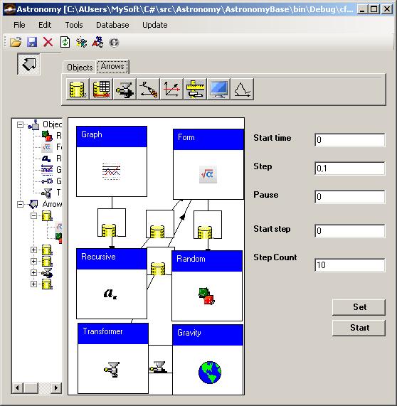
Example of usage
To begin working with this software, it will useful to consider some examples. The first example is devoted to relative motion. The situation of relative motion is shown below.
We have two fixed reference frames (Frame 1 and Frame 3), and we define a motion trajectory of Frame 2 relative to Frame 1. We wish to define the parameters of the relative motion of Frame 2 with respect to Frame 3.
First of all, we should set two fixed reference frames. We put two objects on desktop. These objects correspond to Frame 1 and Frame 3. Then we use the property editor of each object.
This editor enables us to enter the coordinates and the transformation matrix of reference frame. After this action, we will define the formulas of Frame 2. We use the component for this purpose. We enter seven formulas. The first three define: x(t), y(t), and z(t). The last four formulas define angular evolution (we use the components of orientation quaternion). Then, we put the object that is a moved reference frame. Then, we connect all the objects as in the diagram below:
You can download this situation. The directions of the arrows coincide with the association direction. An arrow from Frame 2 to Frame 1 means that Frame 2 knows about Frame 1, since the position and orientation of Frame 2 depends on the position and orientation of Frame 1. However, Frame 1 should not know about Frame 2. Similarly Frame 2 knows about Motion equations. The final step is a setting the component for relative measurements and for the graph indication of the relative motion parameters. The property editor of the graph indicator enables us to show the parameters of the relative motion as in the picture below:
This example is very simple. However, we can use a lot of reference frames, like it is exposed in the following picture:
We have the relative motion and the relative motion parameters of these frames. We can link a virtual video camera, a celestial body, or a spacecraft with every frame. Then, we can to observe the coelosphere through a virtual camera.
So we have an excellent tool for virtual reality. It is only one of the features of this software.
Using the code
The extension of this code includes the creation of new kinds of objects and arrows. Every object should implement the ICategoryObject, and every arrow should implement the ICategoryArrow. Moreover it should be possible to create buttons on the toolbar. The code looks like this:
PaletteToolBar ObjectsToolOb = new PaletteToolBar(tools);
ObjectsToolOb.ImageList = imageListOb;
new PaletteButton(ObjectsToolOb, (int)MathButtons.ZFModule,
"ModuleRing.EuclideanFinitelyGeneratedModule", "", "Z - mod",
imageListOb.UniversalEngineeringFramework[0], 0, false);
Also, you should to implement the IUIFactory interface. This interface creates objects and arrows. Creation of objects looks like:
ICategoryObject IUIFactory.CreateObject(PaletteButton button)
{
if (button.Kind == (int)ButtonKinds.DrawSeries)
{
return new DataPerformerUI.DrawSeries();
}
if (button.Kind == (int)ButtonKinds.DataSetSelection)
{
return new DataSetSelection();
}
return null;
}
Similarly, the creation of arrows is shown. If you wish to create property editors for object or arrows, then you should extend the IUIFactory.CreateForm method. It looks like:
System.Windows.Forms.Form IUIFactory.CreateForm(INamedComponent comp)
{
if (comp is IArrowLabel)
{
IArrowLabel lab = comp as IArrowLabel;
ICategoryArrow arrow = lab.Arrow;
}
if (comp is IObjectLabel)
{
IObjectLabel lab = comp as IObjectLabel;
ICategoryObject obj = lab.Object;
if (obj is IteratorGLM)
{
return new FormIterateGLM(lab);
}
if (obj is VectorFormulaConsumer)
{
return new FormVectorConsumer(lab);
}
}
return new DefaultForm(comp);
}
Points of interests
Since the time of the development of this framework, many interesting events have happened. Often the framework solved a set of problems those are out of the framework destination. Many times, customers visiting our company would ask us to solve a problem. They'd say: "If you solve this problem I will visit you once again". And we'd answer: "You won't need to wait. We shall solve the problem at once".
Ph. D. Petr Ivankov worked as scientific researcher at Russian Mission Control Centre since 1978 up to 2000. Now he is engaged by Aviation training simulators http://dinamika-avia.com/ . His additional interests are:
1) Noncommutative geometry
http://front.math.ucdavis.edu/author/P.Ivankov
2) Literary work (Russian only)
http://zhurnal.lib.ru/editors/3/3d_m/
3) Scientific articles
http://arxiv.org/find/all/1/au:+Ivankov_Petr/0/1/0/all/0/1


 General
  News
News  Suggestion
  Question
  Bug
Bug  Answer
  Joke
Joke  Praise
  Rant
Rant  Admin
Admin 


