Author’s Notes:
This article is written for experienced developers using the C# language and the Monogame Framework. Monogame is in active development with a new release just published recently. This piece is highly technical and requires that developers be proficient in their chosen language of choice. Therefore there is no information that will enable new programmers to work with the sample code easily.
The title prefix, “Part I”, indicates an expectation that as this project progresses into a war game I hope to develop over time that simulates a major conflict of the 18th century, it is hoped that as new code is developed additional articles will be published with the intent of guiding developers in such a difficult form of game development.
Because this piece is published on both Microsoft and Java Community sites, there is information in this piece that should make it easier for Java developers to develop similar code for their own projects. However, the Java information is limited since such a piece cannot provide code and explanations for both languages as the libraries used are completely different from each other
It should also be noted that there is code in the provided project that is no longer currently used but was left as reminders for further development as the project progresses. Such code is noted in this piece.
Due to the length of this piece, a downloadable Word document is available at the following link…
The complete project for this paper can be downloaded from the following link…
To submit questions to the author regarding the provided information, please email the author at…
Overview
One of the most difficult aspects of developing a game is one in which the genre you would like to develop for is such a niche area of development that standardized tools have yet to be created for it. With the popularity of 3D graphic art and gaming the 2D aspect of this creative endeavor hasn’t kept pace with current technologies to the same degree. For 3D game development there are several popular genres that have a wide degree of support; first-person-shooters, simulations (ie: racing, flying), adventure games, and strategic simulations, which are in many cases simply war games on steroids without the thought provoking challenges that a turn-based game of the same genre can provide. For such development there are excellent tools freely available, the most popular being “Unity”, which also has a wide array of 3rd party support in the form of add-ons that provide tools for all the mentioned game types.
With 2D development, scrolling games have been developed to the point that there are many excellent articles describing how to implement one with quite a bit of sample code along with a few very good toolsets to help a developer in his or efforts.
The one genre in 2D development that has gotten very little or rather uneven exposure in the development area is that of the original turn-based, hexagonal map, war game. And beside the original style of adventure gaming whereby the “maze like” foundations were quite thought provoking, war gaming itself has been considered the top of all such mental challenges and at one time was even promoted for the “over educated”.
However, with a lack of some level of standardized tools for such development, this realm of gaming has probably become one of the most difficult areas in creative activity within the game development field. There are several reasons for this that has been described in a number of texts on the subject.
For starters, the computer AI in such games is at a terrible disadvantage compared to the Human opponent since the Human opponent can take as long as he or she likes to develop tactics and strategies that if done carefully over time will not only defeat the computer AI but yield weak spots in it that can aid the player in increasing their battlefield wins somewhat consistently.
In an article describing such a situation within the “Civilization” series of games it was found in one case that players were able to defeat the AI in one significant area of lumber yields by repeating the creation of forests in a single hex, deforesting the hex through lumber production, and then seeding a new forest to start the cycle over again. The AI in the game could not do this giving the Human player a significant advantage in such production, which in turn allowed the Human player to build wooden-based entities more quickly than the AI could.
Though Firaxis Games has openly admitted that their “Civilization” AI cheats (and pretty unfairly as well), when they realized this weakness (called “lumberjacking”) in their AI, they issued a patch placing the AI and the Human opponent on equal footing in this part of the game, making “lumberjacking” no longer possible by the Human player.
The result of this drawback in turn-based war games is that the AI implemented in such games has to be quite good in order to make the game not only enjoyable but repeatable as well. Thus, turn-based war games require above average AI implementations that are more than just what any pre-made tools can offer.
In addition, the AI implementation has to be suited for the level of war game being developed. In such games there are three primary types of AI that can be used, strategic (large unit formations such as divisions), tactical (medium sized unit formations such as regiments), and squad based where each unit represents a single piece of equipment or a soldier. And in each case the AI implementation, as mentioned, has to be done quite well.
This is not the same as with RTS games (real time strategy) where the Human player is at a disadvantage being that he or she must stay on their toes to do battle with an aggressive AI whereby studying the battlefield for any length of time is not an option. The result is that most such games are not very realistic in terms of technique since in reality, as fast as it may occur, war would never be as fast as a computer emulation would propose unless it was designed to be such as with in-depth military training emulations. The lightning fast movements for example in the “Battlefield” franchise could never occur since Humans cannot react at such speeds normally.
The next area of difficulty in the development of turn-based war games are the graphics employed. With the exception of some tile mapping tools that provide the ability to create maps using hexagonal tiles, the developer still has to use original programming to control the map and the units portrayed on it once it is loaded. And since such maps can have a variety of sizes, no one code base offered will necessarily be able to provide the mathematical calculations for the chosen sizes for any individual developer. That being said, one of the most popular mapping tools is “Tiled” (http://www.mapeditor.org/), which will allow a developer to create large hexagonal maps through a visual interface.
“Tiled” creates maps using the “TMX” format, which is actually code that describes a map to a graphics system. Both “Monogame (with the Monogame.Extended plugin)” (http://www.monogame.net/) for C# and VB.NET developers and “libGDX” (http://libgdx.badlogicgames.com) for Java developers support this file type allowing a developer to display his or her maps somewhat easier than if one were to do it on using just the graphics engine and their tiled images.
This article then will describe one way that a hexagonal map can be created and displayed at the lowest level; using the “Monogame” graphics engine only with individual tiled images.
For Java Developers Only…
Being from the Microsoft side of the fence, I develop in either VB.NET or C# as I am fluent in both. For such a discussion, this does the Java Community little good to only have my sample code as a base-line for their own efforts. As a result, I have done a bit of research for Java developers who want to use their language for game development. As mentioned in my previous article, Java is not very high on the list for use in game development but it is getting more tools to work with.
So for starters, Java Developers who want to try their hands at war game development would want to first get a hold of the Java graphics engine, “libGDX”, which can be freely obtained at the link provided above. You will also find some very good books that can be purchased either from the “libGDX” site or from Amazon. And unlike on the “Monogame” side of things, Java developers have an advantage in that that these books appear to be recent publications. We “Monogame” developers still have to rely on XNA documentation but this will change in time as “Monogame” continues to move away from this discontinued platform and becomes it’s own standard as it has started to with it’s latest release, which no longer relies on any XNA framework technologies but is now providing direct support for “DirectX” and “OpenGL”.
Now that you have a good game engine you will also need to understand the differences between my C# code and what you would do with Java. An excellent article on the Microsoft’s Community web site, “The Code Project”, provides a rather extensive side-by-side example of Java and C# code, which includes the gaming code as well. It may not be totally complete but from the looks of this piece, it should provide you with a good grounding to understand what I have done. The article can be found at the following link… http://www.codeproject.com/Articles/754354/Port-a-D-libgdx-game-to-MonoGame
There is also a rather extensive set of tutorials for using “libGDX” with Java at the “Games From Scratch” web site, which can be found at this link… http://www.gamefromscratch.com/page/LibGDX-Tutorial-series.aspx
C# and Java Developers… Let’s begin
Please note that Monogame still uses the Microsoft XNA namespaces for compatibility purposes with prior releases of this engine. This is expected to change in a future release.
When working at the lowest levels in game design such as with the “libGDX” or “Monogame” engines or directly with either “DirectX” or “OpenGL”, such infrastructures often provide for pre-defined “game loop” events and methods that you have no control over. Thus to work with these constructs successfully you have to understand them to bend them to your will. Since the “game loop” processing runs in a continuous cycle you have to ensure that all of your own code falls in line properly with such requirements or nothing in your game project will run correctly. Note that the “libGDX” engine does not provide explicit “game loop” internals as “Monogame” does, though it provides for the same set of “game loop” events through an “Application Listener”. However, there are implied internals that a Java developer can take advantage of through his or her own coding.
To begin with then, after you have installed either “libGDX” or “Monogame” you first must create a new project. With “libGDX”, as far as I can tell, you will be offered a dialog box with a number of options for you to initiate your project with. Not being a Java developer I am taking this information from the “libGDX” site documentation, which demonstrates the use of a “libGDX” platform add-on to do this called “Gradle”. See the “Gradle” interface below…

“Gradle” allows you to set up your project for the platform you would like to build your game for. In our case, we would want to select “Desktop”. By the way, “Gradle” will interface with the following popular Java development IDEs…
- Eclipse
- Intellij IDEA and Android studio
- NetBeans
- Commandline
With “Monogame”, we simply select the type of project we want by selecting from the installed list of “Monogame” templates in Visual Studio as shown below. As a note, those who are Visual Studio developers should ensure that they are using Visual Studio 2013/2015 on a 64bit machine… The 64bit machine requirement will be explained later in this piece.

In our case we would want to select the “Monogame Windows Project”…
Once you initiate the creation of your project, two things will be defined for you. The first is the link to your framework’s internal “game loop”. The “game loop” cycles through repetitively listening for actions that fire one of the events that are now defined in your primary game module. It should be noted that “libGDX” does not have an explicit “game loop” since it is a purely event driven game engine. However, it does have implied “game loop” mechanisms, which Java developers can take advantage of. This information is cited in the article at the link previously provided.
So in the case of Java and the “libGDX” engine, you will have the following events defined in your primary module…
| Method Signature | Description |
| create() | Method called once when the application is created |
| resize() | This method is called every time the game screen is re-sized and the game is not in the paused state; it is also called once just after the create() method |
| render() | Method called by the game loop from the application every time rendering should be performed; game logic updates are usually also performed in this method |
| pause() | On Android this method is called when the Home button is pressed or an incoming call is received; on desktop this is called just before dispose() when exiting the application; a good place to save the game state |
| resume() | This method is only called on Android when the application resumes from a paused state |
| dispose() | Called when the application is destroyed; it is preceded by a call to pause() |
For C# we will have the following similar events defined for us in our “Game.cs” module, a result of the “Monogame” project initialization…
| Method Signature | Description |
| Constructor() | Initializes a default graphics device manager instance; sets up the internal pointer for your internal content; you may also add any global initializations in this method you may require |
| Initialize() | Allows the game to perform any initialization it needs to before starting to run; this is where it can query for any required services and load any non-graphic related content; calling base.Initialize will enumerate through any components and initialize them as well |
| LoadContent() | Will be called once per game and is the place to load all of your content from the “pipeline” |
| UnloadContent() | Will be called once per game and is the place to unload game-specific content that is no longer required (this method does not appear to be used often) |
| Update() | Allows the game to run logic such as updating the world, checking for collisions, gathering input, and playing audio |
| Draw() | Called when the game should draw\redraw itself (ie: after user input) |
To see the exact correlations between the sets of events\methods between the Java and C# languages see the section titled, “Game Loop” in the cited “Code Project” article.
Creating Your Class Level Declarations for the Primary Game Module
Whether I write in VB.NET or C#, I always compartmentalize my module code into specific areas in the document. In Visual Studio these are referred to as “Regions”, which can be expanded or collapsed by the developer for legibility. “Regions” merely provide comment headers to each area and can be nested within each other as well. “Regions” allow for the immediate recognition of the types of code contained in each. There is no equivalent in Java per-se since such a feature is based upon the IDE that a Java developer uses. Thus the posting at the following link can assist Java developers in incorporating them into their specific IDE if they have not already done so… http://stackoverflow.com/questions/2344524/java-equivalent-to-region-in-c-sharp
As to my own class level declarations for the primary game module, I have defined the following assignments…
#region Class Level Declarations
private int ciScreenHeight = 600;
private int ciScreenWidth = 800;
private int ciRowPosition = 0;
private int ciColumnPosition = 0;
private string csScrollDirection = "";
private MGWorkBench_ScrollingHexMap.Classes.TileMap coTileMap;
private MGWorkBench_ScrollingHexMap.Structures.HexTexture2D coHexTexture2D;
private Microsoft.Xna.Framework.Input.KeyboardState coKeyboardState;
private Microsoft.Xna.Framework.Graphics.Texture2D coTexture2DTile;
private Microsoft.Xna.Framework.Graphics.SpriteBatch coSpriteBatch;
private Microsoft.Xna.Framework.Graphics.SpriteFont coSpriteFont;
private Microsoft.Xna.Framework.GraphicsDeviceManager coGraphicsDeviceManager;
#endregion
The two top lines, which are commented, are simply reminders on how to size the game screen to the full size of the user’s monitor or laptop screen.
The next two declarations, “ciScreenHeight” and “ciScreenWidth” define the actual size of the game screen, which will be used in another method to instantiate the actual game screen. And since we will be using a rather small set of hexagonal tiles on our map board, a full sized screen is not necessary.
Two other notes you should be aware of just for clarification purposes. As a professional software engineer I developed my naming conventions during the time when we still had dinosaurs as pets in our backyards and keeping them there wasn’t very easy. This was before Microsoft came up with their own technique, which I believe they claimed was based off of the original industry convention of Hungarian Notation developed by researcher, Charles Simonyi, at Xerox Parc in the late 1970s. He would later become Microsoft’s Chief Architect.
The Microsoft style of notation only uses a very small aspect of Hungarian Notation, which I believe is quite similar to what may be currently used in the Java language. My level of Hungarian Notation has always been somewhat more precise than the Microsoft style making it similar to the original intent of Dr. Simonyi’s concepts that we used in mainframe development. In it’s true form, Hungarian Notation can be quite complex but in Microsoft’s form it is overly simplistic since it does not denote where a variable is defined. In addition, Hungarian notation was designed to be also used as method name prefixes so that a developer could easily understand where the calling method was in relation to the current one.
Though I do not use any such method prefixes I do use the variable prefixes in “Camel Case” that inform the developer as to where the variable is defined as well as what the variable type is as Microsoft does. In the case above, the two screen size variables are prefixed with “ci”, meaning that they are defined at the class level as integers. Thus a sampling of such notation could be seen as follows, starting with where a variable is defined…
| Definition Area Prefix | Description |
| l | local (within a method, function, or scoped section |
| c | class level declaration (global to the class) |
| f | form level declaration (global to a form module – WinForms only) |
| m | module level declaration only (global to a VB.Net module) |
| p | parameter declaration (found within an argument list) |
| s | structure level declaration (global to a structure) |
The next part of the prefix is of course the variable type and the ones that I normally use are as follows…
| Type Indicator | Description |
| bool | Boolean |
| dec | decimal |
| i | integer |
| dbl | double |
| flt | float |
| o | object (any type; ie: arraylist) |
| s | string |
I have been using this rather simplistic but more precise form of Hungarian Notation for many years without any issues. Some readers will argue that modern IDEs already have intellisense pop-up menus that can easily find where a variable is declared but that also means having to leave the current location in the code in order to see the declaration. Over time and constant use of my form of simplistic Hungarian Notation a developer no longer would require any such tool to understand a variable declaration as he or she will just inherently understand where a variable is defined and it’s type.
The other note I want to mention is that all of the variables found in my class level declaration section can be easily moved into a “Globals” module as many developers do. This is what I am planning on doing as this initial implementation is refined. However, a lot of work went into researching this technique before I began writing this paper so the entire code base is still in a somewhat dynamic state though as you will see, the code does work quite well.
Finally, as it regards this last contention some of the coding and variables defined in my solution may no longer be found to be in use and commented out as result or simply left active. This is because some of the code may be used for further extensions of this design as I allude to in later sections of this paper. In this case, the variable declarations, “ciRowPosition”, “ciColumnPosition”, and “csScrollDirection” fall into this consideration.
The remaining list of object declarations in this code section (ie: “coTileMap”) will be used in upcoming sections to be described.
The “Constructor” Event
To begin simply we will show the amount of code normally reserved for the “Constructor” event. As noted in the descriptions above, this event is used for straight-forward global initializations for your game project. If you prefer, you do not have to put the pointer to the “Content Pipeline” in this event but there would be no reason not to…
#region Constructor(s)
public MGMainGame()
{
coGraphicsDeviceManager = new GraphicsDeviceManager(this);
Content.RootDirectory = "Content";
coGraphicsDeviceManager.PreferredBackBufferHeight = ciScreenHeight;
coGraphicsDeviceManager.PreferredBackBufferWidth = ciScreenWidth;
}
#endregion
The constructor for most such games will be rather simple. In this method you only need to put one time initializations that will be immediately required by the internal game loop. In this case we have three forms of initialization…
- Graphics Device Manager with the parameter as that of the current game module; this line of code is generated by the Monogame framework.
- Content Root Directory, which is the internal pipeline to all of your game images that in the case of Monogame are converted into “xnb” files for quick access; this line of code is generated bythe Monogame framework.
- Actual Screen Size for the display defined by the developer(note that with Monogame to size the screen you use the “Preferred Back Buffer”)
A Note on the Content Pipeline
All games have some type of content pipeline, which is merely a way that a game accesses it’s graphic assets. Though “libGDX” does not use an explicit one that I can find, a Java developer still must somehow provide access to the game graphics he or she intends to use for their game. In the case of the documentation I have read so far for the “libGDX” game engine, it appears that graphic references are made explicitly in the same fashion that one would access a text file from code.
However, with “Monogame”, this process is made more convenient for the developer by providing a centralized sub-directory that can access graphic images simply by their file names without any file extension requirement.
To get your images into the “Monogame” pipeline, you must add them in the following manner… And this is why you require a 64bit machine for Monogame development as I stated earlier. The Content Pipeline interface application is a 64bit program. Without a 64bit machine, you will not be able to use this interface, requiring you to access your images in the same way a Java developer would do with the “libGDX” game engine.
1… Expand the folder labeled “Content” in your “Monogame” project (Visual Studio project is shown)

2… Double-Click on the file, “Content.mgcb”. This should open the “Monogame Content Pipeline Tool”

3… If the above tool does not open up but you instead get a text file, listing the information regarding any existing asset information than you should set the “Content.mgcb” file to the default application by using the “Open With” command on the Right-Clicked dropdown menu that will allow you to set the default…

4… In the Content Pipeline tool add a new graphic asset by doing the following…
- Right-Click on the “Content” root folder in the left-most pane
- Select “Add”
- Select “Existing Item”

By adding a graphic image this way, “Monogame” developers will be able to access the Content Pipeline image directory directly for quick loading of their images for use within their game project.
The “Initialize ()” Event
Like all classes in our development environments, the primary game module has an “Initialize” event. There is no need to put anything within this event unless you want to implement your own, required initializations for your project. Like, most of the events in the primary game module, this event will only be called once.
The “LoadContent ()” Event – Actually Loading Your Graphic Content
Normally you load the bulk of your content once at the beginning of the initialization of your game project, leaving possible, additional assets for later as they are needed. In “Monogame” then, this is done with the “LoadContent” event. In this project we will use the following code for this event…
#region LoadContent Event
protected override void LoadContent()
{
coSpriteBatch = new SpriteBatch(GraphicsDevice);
coTexture2DTile = this.Content.Load<Texture2D>("Grass_72x72");
coSpriteFont = this.Content.Load<SpriteFont>("MySpriteFont");
coHexTexture2D = new MGWorkBench_ScrollingHexMap.Structures.HexTexture2D();
coHexTexture2D.TEXTURE2D_ID = 1;
coHexTexture2D.TEXTURE2D_IMAGE_TILE = coTexture2DTile;
MGWorkBench_ScrollingHexMap.Structures.Global.TEXTURE2D_ARRAY_LIST.Add(coHexTexture2D);
}
#endregion
The code above is implemented by both the Monogame Framework as well as the developer…
- The first line of code, which creates a new class level instance of the “SpriteBatch” is generated by the Monogame Framework, the instance variable, “coSpriteBatch”, changed by the developer for programmatic consistency
- The rest of the code is defined by the developer; it should be noted that the structure initialization code is not in any way used in the project but is a holdover from previous testing. You may ignore this code in your development projects, which use this code as a reference.
Note that the “SpriteBatch” variable will not be used here but in the “Draw” event. It is defined in the this event to avoid having to re-declare it every time the “Draw” event is called.
The Hexagonal Tile
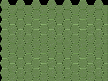
To develop this project as simply as possible so that I could concentrate on accomplishing the main goal of displaying a scrollable hexagon map, I used a single hexagon tile, reflecting dark, grassy, meadowland, with dimensions of 72 pixels by 72 pixels, a perfect square.
When researching information about the development of hexagonal tile maps you will often find references to such entities as rectangles, which they are. However, in reality, for this type of work, a square is also considered to be a rectangle mathematically. If one were to simply view tiles as rectangles an assumption could be made that actual non-square rectangles could be used as well. They can but determining positioning and offsets can also get more complex as a result. Given this, any tile of square dimensions can be adjusted and calculated for much easier than actual rectangular tiles can.
The image of the hexagonal tile that I used for this project can be found below…
 72px by 72px (px=pixels)
Notice the gray and white checkered area surrounding the actual hexagon itself. This is the background transparency for the entire image and will allow us to overlay parts of the hexagonal images over each other as shown below.

Note that I overlaid the lower image by hand using Paint.NET so if you notice that the images look slightly out of alignment you would be correct. In the actual game screen they are perfectly aligned as a result of the calculations behind the alignments. Also notice where the lower hexagon aligns to the upper one; it is placed halfway down against the upper hexagon (the eventual “Y” coordinate) and adjusted to the left (the eventual “X” coordinate). These adjustments will be noted in the project as the “X” and “Y” offsets.
Using perfect squares for hexagonal tiles will make your development efforts much easier than using actual rectangular tiles unless of course you have a reason for using them. Square tiles make determining your offsets far easier. And square tiles can be of any size your project will require, though using anything smaller than 32px by 32px will make overlaying unit icons or implementing recognizable terrain emplacements (ie: breastworks) rather difficult to accomplish image-wise.
The Orientation of Hexagonal Tiles
In my project I use what are known as “flat topped” hexagonal tiles since a side of the tile is at the top of any tile. It is merely a personal preference. The other type of hexagonal tile is called “pointy topped” since one of the points of a tile is at the top of the tile.

You may use either type in your own projects but you have to remember that the calculations for offsets and placements will be somewhat different for each type. As a result, the calculations in this project will not work for “pointy topped” hexagonal tiles.
The best information on the Internet for the geometry, calculations, and algorithms used with hexagonal tiles can be found at the site for “Red Blob Games”, which is being maintained by Amit Patel, who is a software developer and computer scientist. You can access his site at the following link… http://www.redblobgames.com/
Please note that Amit does not provide any actual graphics programming support at his site.
The “Update ()” Event
The “Update” event is an event that is continuously called by the internal “game loop”. It constantly listens for user input into the game. As a result, this is where all of a user’s interaction with the game interface is handled within the primary game module. A number of tools have been developed for Monogame, which can be used to design more complex interfaces that many games will require. One such tool is “EmptyKeys” and is considered the best of the freely available tools for Monogame development. The “EmptyKeys” toolkit can be found at the following link… http://emptykeys.com/
For Java developers deciding to try their hand with using “libGDX”, this library also has an interface extension (VisUI) that appears to be similar in capability to “EmptyKeys”, which can be found at the following link… https://github.com/kotcrab/vis-editor/wiki/VisUI
For my own project’s purposes implementing basic scrolling of a hexagonal map board was the primary goal. So for now, I merely implemented the calculations in the “Update” event that would accomplish this. As can be seen in the code below, left, right, up, and down scrolling has been implemented…
#region Update Event
protected override void Update(GameTime gameTime)
{
if (GamePad.GetState(PlayerIndex.One).Buttons.Back == ButtonState.Pressed || Keyboard.GetState().IsKeyDown(Keys.Escape))
Exit();
csScrollDirection = "";
coKeyboardState = Keyboard.GetState();
if (coKeyboardState.IsKeyDown(Keys.Left))
{
csScrollDirection = "L";
ciRowPosition = ciRowPosition + 0;
ciColumnPosition = ciColumnPosition - 1;
MGWorkBench_ScrollingHexMap.Classes.Camera.coCameraVector2Location.X =
               MathHelper.Clamp(MGWorkBench_ScrollingHexMap.Classes.Camera.coCameraVector2Location.X - 2,
               0,
               (MGWorkBench_ScrollingHexMap.Structures.Global.ACTUAL_TILE_WIDTH_IN_PIXELS – 14));
}
if (coKeyboardState.IsKeyDown(Keys.Right))
{
csScrollDirection = "R";
ciRowPosition = ciRowPosition + 0;
ciColumnPosition = ciColumnPosition + 1;
MGWorkBench_ScrollingHexMap.Classes.Camera.coCameraVector2Location.X = MathHelper.Clamp(MGWorkBench_ScrollingHexMap.Classes.Camera.coCameraVector2Location.X + 2, 0, (MGWorkBench_ScrollingHexMap.Structures.Global.ACTUAL_TILE_WIDTH_IN_PIXELS + 14));
}
if (coKeyboardState.IsKeyDown(Keys.Up))
{
csScrollDirection = "U";
ciRowPosition = ciRowPosition + 1;
ciColumnPosition = ciColumnPosition + 0;
MGWorkBench_ScrollingHexMap.Classes.Camera.coCameraVector2Location.Y =
               MathHelper.Clamp(MGWorkBench_ScrollingHexMap.Classes.Camera.coCameraVector2Location.Y - 2,
               0,
               ((MGWorkBench_ScrollingHexMap.Structures.Global.MAP_TILE_OFFSET_Y * 14) + 14));
}
if (coKeyboardState.IsKeyDown(Keys.Down))
{
csScrollDirection = "D";
ciRowPosition = ciRowPosition - 1;
ciColumnPosition = ciColumnPosition + 0;
MGWorkBench_ScrollingHexMap.Classes.Camera.coCameraVector2Location.Y = MathHelper.Clamp(MGWorkBench_ScrollingHexMap.Classes.Camera.coCameraVector2Location.Y + 2, 0, ((MGWorkBench_ScrollingHexMap.Structures.Global.MAP_TILE_OFFSET_Y * 14) + 14));
}
base.Update(gameTime);
}
#endregion
Developing these calculations was quite a bit of work as I had originally based them off what was considered a standardized tutorial for hexagonal map development for the Microsoft original XNA environment. Though the tutorial’s code worked as provided, it was based off a very odd set of dimensions for hexagonal tiles. One would think that by using perfectly square tiles, such calculations would be able to be adjusted fairly easily. They weren’t and what I found was that in fact the tutorial’s math could not be used at all so I had to literally re-invent the wheel to make such calculations rather generic. Thus, as long as you elect to use tiles with dimensions of a square, you should have no trouble adjusting my calculations for your own.
To the above code…
As you will see the first test is for whether a game-pad Back button has been selected or that of a keyboard’s “Esc” key. In either case, the application will be ended closing the game screen.
The next four blocks of code test for whether the Left, Right, Up, or Down arrow keys have been depressed. For each key an appropriate calculation is made for the corresponding direction that the map board should move.
Before we get into the actual calculation, please note that the code affecting the following three variables, “csScrollDirection”, “ciRowPosition”, and “ciColumnPosition” can be completely ignored for our purposes. These lines of code have been left in place for later developments that may require them.
The Camera
To begin with, these calculations are based off what game developers call a Camera”, which is simply a construct that allows a player to view the game screen from a certain angle or direction. However, with 2D game screens involving top-down views of a playing board, one more or less has a choice as to how a camera should be used. In our case, all we require is the default camera that is immediately available as a result of the “Monogame” engine. In this case, we will not move the camera but instead move the playing board in the direction we want it to move. You do have the option if you want to add some mathematical complexity to your development of creating an actual camera and moving that over the game board in similar style. Not wanting to get into “matrix transforms” and wanting to keep things simple, I opted for moving the map board.
Though the “Monogame.Extended” toolkit provides easier access for an actual camera to be instantiated, we will simply define our camera as a “Vector2” object that will simply keep track of the actual screen coordinates for the map board. This definition can be found in the class module, “Camera.cs”, in the folder “Classes” within the project solution.
Though this class is defined as an actual “Class”, so far it has only data within it so if I find that no methods will need to be added down the road, I will change it to a “Structure”, which I prefer using under such circumstances.
As you will note, the code for this data is implemented as private variable declaration and an “Internal” property, which for Java developers means that these modifiers can only be seen within the scope of the project. I note this as I am not aware of the Java equivalent if in fact there is one or the same modifier is used.
So that the data is always held internally for later use, everything in this class is defined as “Static”.
For your own purposes you may define a similar construct in the manner you feel most comfortable with but you should remember to provide it with the “Static” modifier or it’s equivalent.
The “Vector2” object in this case will simply keep track of the amount of movement in all four directions. And in all cases, the increment for that movement will always be 2 pixels.
The Movement Calculations
MGWorkBench_ScrollingHexMap.Classes.Camera.coCameraVector2Location.X =
MathHelper.Clamp(MGWorkBench_ScrollingHexMap.Classes.Camera.coCameraVector2Location.X - 2,
0,
(MGWorkBench_ScrollingHexMap.Structures.Global.ACTUAL_TILE_WIDTH_IN_PIXELS – 14));
From the code snippet above you will note that all four of the directional calculations compute the Vector2 “X” or “Y” coordinates. These updated coordinates will always be used in the subsequent “Draw” event, which redraws the map board multiple times within the space of a minute; all of which cannot be interpreted by the Human eye making it appear that the map board is appearing as a constant until some level of user input or game calculation changes the display.
The use of the “MathHelper.Clamp” method is possible since the “MathHelper” class is part of the Monogame namespace, “Microsoft.Xna.Framework”. The “Clamp” processes as it’s first argument the new “X” coordinate. In the above case, for a Left arrow key selection, it simply takes the existing Vector2 “X” coordinate and subtracts 2 from it replacing the “X” coordinate with the new value.
The other two arguments to the “Clamp” method are the “minimum” value allowed and the “maximum” value allowed. In this case, the minimum value would be zero(0) so if the calculation returns a value less than zero(0), the new “X” coordinate will be updated with zero(0). The maximum value on the other hand has to also take into account a value that allows for the left-most map board edge to appear while disallow any further movement to the left once the screen display reaches the left-most edge. We do this by using the actual width of a tile, which is defined as 72 pixels in our “Global.cs” structure, which can be found in the project’s folder labeled, “Structures”.
The subtraction of “14” from the width of a tile is completely arbitrary and will require some testing on your part when using hexagonal tiles that are either larger or smaller than 72 pixels. Thus, if a calculation exceeds the maximum allowed value of (72 -14), the “X” coordinate will then only be provided with a value pf “58”, which in fact is the actual offset defined in the “Global.cs” structure for tiles being rendered along the width of the screen display.
For a movement of the map board to the right, we use the same calculation as above but instead of subtracting from the Vector2 “X” coordinate, we add 2 pixels while adjusting the right most maximum value with +14 instead of -14.
One would think that for a right movement, the maximum value would be the actual width of the tile in pixels multiplied by the actual number of tiles to be displayed across the screen plus 14. I tried this calculation several times to test it out and this is what will happen if you try it with this project’s code…

Notice that the map scrolls correctly to the right but allows you to keep on scrolling in that direction. The reason why the updated calculation would yield such a result is because we are calculating a starting “X” coordinate with each depression of the Right arrow key as to where the map board “Draw” event should begin drawing it’s images that correspond to the actual screen “X” coordinate, which always begins at zero(0). As confusing as this may sound it does make sense since we are tracking the number of pixels we will move right to reach the right-most edge of the map board. Since we are working with a defined map board of 15×15 hexagonal tiles (see “Global.cs” for these declarations) we have to consider not only the number of pixels right we need to attain before reaching the map board edge but the offsets as well for overlaid images.
The same holds true for the logic behind the calculations for Up and Down movements. However, since we do not have to consider offsets as we do when calculating across the screen we then need to consider the entire height of the tile (72 pixels) when calculating for up and down movement.
As just mentioned, the Up and Down arrow key movement calculations have a slightly updated calculation as the Up calculation code snippet code below demonstrates…
MGWorkBench_ScrollingHexMap.Classes.Camera.coCameraVector2Location.Y =
MathHelper.Clamp(MGWorkBench_ScrollingHexMap.Classes.Camera.coCameraVector2Location.Y - 2,
0,
((MGWorkBench_ScrollingHexMap.Structures.Global.MAP_TILE_OFFSET_Y * 14) + 14));
In these two cases instead of calculating the Vector2 “X” coordinate we calculate the “Y” coordinate. For an Up movement we subtract 2 (pixels) from the existing “Y” coordinate. For a Down movement we add 2 (pixels).
The minimum value allowed is again zero(0) while the maximum allowed value
Though I hardcoded the number “14” in my current code, you should consider making it a pre-defined number in a global class so you only have to make changes in a single module to affect all of your calculations wherever you may define them.
The “Draw ()” Event
The “Draw” event is where all of the graphics action occurs with the “Monogame” engine. Like the “Update” event, it is called continuously by Monogame’s internal “game loop”. Why Microsoft designers decided to do this instead of using a more Java oriented, event driven approach is something I do not know and admittedly I have not looked for an answer. Possibly, the Microsoft people saw this continuous cycle as more efficient.
In any event, the “Draw” event in my project is the first place I began to modularize the functionality of the code.
#region Draw Event
protected override void Draw(GameTime gameTime)
{
GraphicsDevice.Clear(Color.Black);
coTileMap = new MGWorkBench_ScrollingHexMap.Classes.TileMap(coSpriteBatch, coSpriteFont, coGraphicsDeviceManager, coTexture2DTile);
coTileMap.Draw_SampleTileMap(csScrollDirection, ciRowPosition, ciColumnPosition);
base.Draw(gameTime);
}
#endregion
The first line of code in this event ensures that the background for our map board is “black”. This means that the edges of the map board will have a black field surrounding them. Some developers like to show their edges as partial hex tiles but since such tiles can’t be used for actual game play, I decided against this to ensure that a player would know where the active tiles begin and end.
The next line of code instantiates a “TileMap” object; this is defined as “TileMap.cs” in the “Classes” folder of the project. As you will note several class level objects in the primary game module are passed to the constructor of this object.
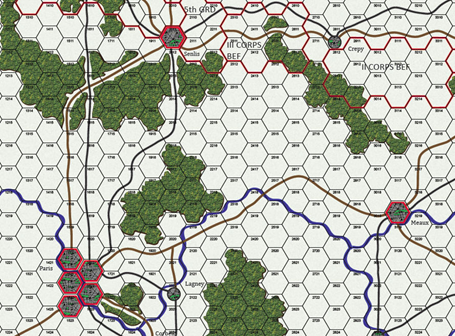
Next, we make a call to the “TimeMap” object to draw the entire map board, which should appear as the image below when the game screen is displayed…
Notice the black field around the map board edges as noted previously. Please also remember that we are using only type of hexagonal tile for the entire map board at this time. Also note the tiles perfect alignments with each other due to the drawing/positioning calculations.
For those not familiar with any level of game programming just being able to develop the above image is quite a piece of work no matter how many articles you may find beneficial for your research. This is why I have tried to make my project as standardized as possible for the hexagonal tile sizes.
The last line of code, which is generated by the “Monogame” framework, provides the application with it’s own internal game timing values. With all my research on this aspect of XNA\Monogame I never found any real explanation for this requirement for the “Monogame” infrastructure. However, since it is required do not remove it.
From this discussion on the “Draw” event so far, it appears to be rather simplistic but it is hardly that. So let’s take a look at the code of the “TileMap object along with the “TileMapLoad” object and the “HexTile” structure…
The “TileMap”, “TileMapLoad” Objects & the “HexTile” Structure
The “TileMap” object or class was implemented to centralize all of the code required to handle the map board displays. If you have looked at articles on the display of tile maps you would have found that such a class is fairly standard practice.
As mentioned in the piece previously, not all of the code is currently in use, while some of it was simply implemented for experimentation purposes and though still active, is not used. The properties at the top of this class in the “Class Internal Properties” region are just such code sections. They have been left in the class for possible later purposes.
As you will note within the “Constructor”, the passed objects are loaded into their corresponding class level object declarations. However, in addition, this is where we also load the entire map board into an internal, two dimensioned array. Again, this is fairly standard practice for the display of tiled maps.
If you review this processes method, “Load_MapHexTileArray ()”, you will see that the structure, “HexTile” (“HexTile.cs”) is used as the element that is being loaded into this array (another fairly standard construct in such development). However, within this method we instantiate the “TileMapLoad” object, which is the sub-class that will handle all such map loads (“TileMapLoad.cs”).
This class is instantiated with the actual height and width of the map board in terms of the number of tiles to be displayed in each case. Since we are using these numbers from the “Global.cs” class, there is actually no need to instantiate the “TileMapLoad” object in this manner as these variables could have been simply used in the “TileMapLoad” class itself. Nonetheless, these variables will be used to define the size of the two dimensional map board array.
If you notice with the “HexTile” structure that is being loaded into the array, there is no property as of yet for the image that each tile is to display. There are good reasons for this at this point. One, for simplicity’s sake we are using a single type of map tile so at the time there was no necessity to include the tile image as part of the array or any form of reference to it. This will also be noted later as we move into the actual drawing code itself.
The second reason is that to include such images or image references within the “HexTile” object, you have to know what images you plan on displaying in each position for the initial map board. You also have to build in potential allowances for secondary images that may be used for the same positions during game play. For example, if a unit builds an entrenched position on a particular map tile you would want to have the “HexTile” object be able to have such a reference in order that when the map is re-drawn after this building of an entrenchment the proper image is displayed. All of this however, takes a bit of design work with either a hex map editor tool such as “Tiled”, the link for which was noted at the beginning of this paper or by pencil\pen and paper on a printed sheet of hexagonal tiles. For the latter, you can find a freely available, online tool at the following link… http://incompetech.com/graphpaper/hexagonal/
Once we get into the “TileMapLoad” class you will find two methods have been implemented…
- Load_MapHexTileArray()
- Transform_MapHexTileArray()
The “Load_MapHexTileArray” method is the one we are interested in. We will come back to the “Transform_MapHexTileArray” method later.
The “Load_MapHexTileArray” method is and will remain the primary method for loading “HexTile” structures into the two dimensional array. The most important aspect of each hex tile is whether it will be drawn in an even column (0, 2, 4…) or an odd one (1,3,5…). This consideration is also fairly standard for this type of development. However, some developers prefer to orient this consideration for even and odd rows. I started working with the even\odd column construct and there was no reason to change.
If we draw a hexagon tile in an even numbered column, there is no need to be concerned about a “Y” coordinate-based offset since the first hexagonal tile in such columns will always be drawn starting from the top of the map board. If the tile is to be drawn in an odd column we have to then consider the “Y” coordinate-based offset. Thus for such columns, the “Y” offset will be 36 pixels or simply half of the height of a tile. This is one good reason to use completely square tiles instead of some form of an actual rectangle.
The rest of the information that is provided for a “HexTile” structure is relatively straight forward…
- A tile-id, which can be used later to determine how to select an image from an image map sheet; if you decide this to be the most efficient way of loading your own images. For our immediate concerns the tile-id is a simple, numeric count. In terms of efficiency it makes no difference how you load such content since all of the necessary content has to be loaded at some point taking up around the same amount of memory.
- The row-id and column-id are also standard properties for such a construct as each tile’s coordinates are necessary for latter development against their use such as calculating which tile a user selects. In this case, there are quite a number of algorithms that can be used for such functionality, some of which can be found at the “Red Blob Games” site, the link for which was provided earlier in the paper.
Over time then it is expected that the “HexTile” class will grow in terms of it’s necessary properties. However, for our purposes now, the basic information currently provided is more than enough.
The TileMap Code
Returning to the “TileMap” object we can now concentrate on the primary drawing method, which is the “Draw_SampleTileMap” method. As mentioned previously, this method is called from the primary game module. However, it is in the “TileMap” class that the actual drawing gets performed.
The method currently takes three arguments…
- psScrollDirection
- piRowPosition
- piColumnPosition
The “psScrollDirection” parameter has been used for testing purposes but may be needed for further development down the road. The other two parameters can be ignored. They were originally intended to be used for directional movement based on tiles instead of pixels. These two parameters were originally implemented as part of my research into this type of development. However, they may later serve as needed information for tile selection.
After the initial declarations within the “Draw_SampleTileMap” method you will find two lines of code that have been commented out…
This code was implemented previously with the idea (just mentioned) that directional movement would be controlled based on a tile-by-tile basis instead of pixels. The called method, “Transform_MapHexTileArray”, was designed to calculate, which tiles would be displayed by zeroing out the tile-id in those elements in the two dimension tile array that would not be shown. The method actually worked in terms of the tiles to be displayed for each movement direction entered by the depressing of an arrow key but made the movement very choppy and inaccurate. And as you can see it is this method that uses the variables, “piRowPosition” and “piColumnPosition”, which the above information stated that you could ignore. The result was that this technique was dropped but the code has been retained for future reference as a similar process is expected to be required for the transformation of images that require changing during game play.
The next line of code initiates the actual “Monogame” drawing code with the statement, “coSpriteBatch.Begin();”. This code informs the “Monogame” framework that the drawing cycle is to be initiated.
It is within this cycle that the most common of tile map display coding will be found for all games of similarity of this genre of development. This is where the hex tile two dimensional array is looped through to extract the information for positional display.
The first aspect of this code section and before the actual display loop begins is to define where the drawing is supposed to begin in terms of the display screen’s coordinate system. To the new game developer it would appear that the code would provide display positions in the game screen to the right or left of the zero(0) “X” coordinate as well as the same for up or down against the zero(0) “Y” coordinate. This is obviously most confusing and took me quite a while to understand the difference here since in reality, it makes little sense. However, if we look at the Vector2 object and the displayed game screen as two separate entities that internally align with each other than sensibility comes into the equation.
In this instance then, the Vextor2 object defines where in the images to be display the “X” and “Y” calculated coordinates are to begin selecting the image data. So for example, if these two coordinates were to begin as X=2 and Y=2 than this would mean that extracting the image data would begin in similar style at these coordinates as if such data represented an actual graphical playing board. To take this example further with a tile-based framing reference we could look at the image below in such a manner in the following way…
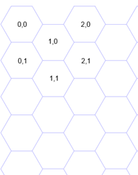
If the hexagonal tile labeled “0,0” represents X=0 and Y=0 for tile based coordinates than if the game display loop began with hexagonal tile, “1,1”, the actual screen display would actually begin drawing this tile at screen coordinates, “0,0”. Thus tile, “1,1”, would be drawn in the upper left corner of the physical screen display. This appears to make no sense but it does since a gaming engine that tied the default camera (in this case) to the actual calculated coordinates instead of the physical screen coordinates would not work properly as everything would be offset except for the “0,0” coordinates of the imaged map board.
The game display loop in this project displays by the column. Many game developers prefer to display by the row. It is a personal preference and also related to how you learned how to develop such code for hexagonal image displays. In this case we begin the outer loop with the “Y” index and the inner loop with the “X” index, both against the two dimensional tile array…
for (int liY = 0; liY < (MGWorkBench_ScrollingHexMap.Structures.Global.ACTUAL_MAP_HEIGHT_IN_TILES); liY++)
{
    for (int liX = 0; liX <  (MGWorkBench_ScrollingHexMap.Structures.Global.ACTUAL_MAP_WIDTH_IN_TILES); liX++)
The result then is that for every tile represented in the two dimensional array we do the following…
- Extract the “HexTile” structure
- Test for whether that tile is to be placed in an even column or an odd one
- Calculate the new hex tile “X” and “Y” coordinates for which type of column the tile is to be drawn in
- Physically draw the image to the physical screen
Two notes concerning the body of this code…
First, the commented line of code below relates to the previously described transform method which is not being used at this time…
Final Notes
I have no doubt that readers may have many questions and/or comments related to this piece and the corresponding source code. No doubt, this was a very difficult piece to write. It is not only highly technical but delves into an area that few other developers in the game industry, whether as hobbyists or professionals, have spent much time in explaining adequately. This lack of information is mostly the result of the decreasing interest in the war game genre in the past years. It is also a result of the fact that developing such games is extremely difficult and complex.
Nonetheless, there are some silver linings here. One, a recent report of the technology profession in general has found that game development is becoming one of the hottest areas of professional and hobby development to be involved with. This is a result of the introduction of excellent 3D tools that are not only offered freely but allow a game developer to create literally any type of game he or she could imagine. This growth area in the industry appears to have reignited a slow resurgent interest in the war game as well.
Being that the war game not only involves technical development but history and the ability to plan in-depth strategies and tactics, it is possible that many people who have become tired of the mindless violence portrayed in many current games may begin to return to one of the most popular gaming genres in history outside of the card game.
I hope this first article I have developed for your enjoyment of the development aspect of this gaming genre helps to renew such interest. If I have made some technical mistakes or misinterpretations, please note that though I have spent years researching and following the game industry, this is the first time I have had the time to tackle the technical development aspects of the genre I have always been most interested in since the 1990s. This last is also the reason why my project’s source code appears to be in a state of flux.
I hope you have found this article both informative and challenging. If you have any questions, comments, or suggestions as to how some of the code may be changed or how an explanation may be modified, please drop me a line at the email address above. I would love to hear from you concerning your views and thoughts on the matter.
In a future article I plan to provide an actual hexagonal map board design and the updated code to support it…
This member has not yet provided a Biography. Assume it's interesting and varied, and probably something to do with programming.


 General
  News
News  Suggestion
  Question
  Bug
Bug  Answer
  Joke
Joke  Praise
  Rant
Rant  Admin
Admin 


