Fig.1 The panel of the test application.
Introduction
When writing a program for step-by-step editing and keeping of a complex document, an idea came into my mind that allowed me to solve this problem in a simple and efficient way.
A bit later, I realized that the way I solved my particular problem represents quite a general approach to a much larger class of problems and hence can be useful to somebody else. That is why I decided to write a short article for your website to share the idea. This could be especially appropriate given that there are not many papers addressing the art of programming.
I would call a class of problems to be dealt with as Wizards. In a sense, any installation process is a simplest example of a Wizard. A user is asked to go through a series of dialogues, choose relevant options and run the installation procedure. Schematically, this chain of events can be depicted as the following diagram:

Wizard allows a user to jump one or more steps back in order to repeat them again if needed.
In essence, there exists many more processes which could be called wizards and represented by a scheme similar to that in Fig 2. To name a few, we mention the processes of:
- filling the forms and performing complex transactions in data management,
- testing and setting up numerous devices,
- calibrating measurement devices.
This list is fairly incomplete, and readers may easily continue it by adding examples of their own.
In a more general way, a wizard-type problem can be formulated as follows: there exists a set of tasks; they are performed in a certain order which is determined by some logical considerations dictated by a particular application.
Importantly, a Wizard differs from the usual stream diagram. The engine of a stream diagram verifies if a task can be performed; it runs a task automatically only if a task can be executed. For instance, if a task is some function, the function will be executed once the function parameters are made available.
A Wizard has a peculiar feature: the tasks are not automatically executed; they are run manually by the application user while the engine of a Wizard simply detects what tasks are available for running at each time instance and allows the user to run them. However, it is the user who eventually decides what tasks will be performed and when.
Let us consider a process depicted in Fig. 3. It consists of 5 tasks. Notice that the tasks No. 1 to No. 3 do not depend on other tasks and can therefore be executed in any order at any time. The task No. 4 may only be done after both the task No. 1 and No. 2 are completed. The task No. 5 may be run once the tasks No. 3 and No. 4 are completed.
If, at this time, one has to run the task No. 2, both task No. 4 and No. 5 can be performed anew as well. An important remark is in order: if a task was performed anew and there exists other tasks whose results depend on this task, these other tasks have to be run anew as well. Such a problem is also of a Wizard-type albeit it is a bit more complicated. At each step, a user is interested in two issues:
- What task can (or should) be done?
- What tasks are yet to be performed?
A programmer problem is somewhat more complicated: he or she should know how such a logic could be implemented? As a rule, everything is done in a traditional manner. At each step, one analyses a current state of the process and makes a decision. For instance:
if (IsDone(Task1) && IsDone(Task2) &&
          IsDone(Task3) && IsDone(Task4) && !IsDone(Task5))
{
    …
     Done(Task5);
    …
}
In case that the number of tasks is large, and the links between them are complicated, the presented solution becomes hopelessly cumbersome. In addition, a tiny change in logic would lead to the need of making significant alterations of the code. Its debugging is a problem in its own right…
Is there any way to make our life easier? I claim that there is a way that saves time. I will explain it in the following section. Let me just notice that my solution is by no means the only solution.
Computational model
Representation of the task via diagrams similar to the one in Fig. 3 is a starting point for building a computational model. Any task can be put represented by a functional block, see Fig.4.
The box represents a task has two major attributes:
- List of input conditions.
- List of output conditions.
The input conditions are given by a vector of boolean variables. A task can be performed if all the variables are set to true.
Obviously, this blocks certain functionality: a certain action is attached to each task (transaction, calculation, input/output act etc.) However, at this point, we are interested in the fact of performing or not performing a task rather than in its concrete sense.
Once a task is performed, a vector of output variables is set to true.
It should be mentioned that input and output conditions set the links between the tasks. The above model allows one to build an automatic solver which would be able to answer, at each stage of the process, two questions formulated earlier:
- What task/tasks can (or should) be done?
- What tasks are yet to be performed?
Implementation of the model
A system is implemented in C#. The only reason for choosing this language is that it is the current environment at my workplace. One could equally use Java, C/C++, DELPHI etc. The solution is attached to this article. Below, I will explain the major points in the implementation:
1. Task
The class Task corresponds to the notion task. This class implements the interface ITask. The most important elements of this interface are:
- The method
Done; it imitates a procedure for performing a task.
and
- Property
IsDone; it allows one to verify if the task was or was not done.
The input parameters of the constructor of the class Task are: the task's identifier, lists of input (radarIsReady, operatorIsReady) and output (detectionIsDone) conditions (the object Condition will be described in pp2):
ITask objectDetection
    =    new Task("ObjectDetection",
            new Conditions(detectionIsDone),
            new Conditions(radarIsReady,operatorIsReady))
;
A set of objects of the type Task comprises a system. This system is implemented by means of the object with the interface IEnvironment.
Function Done realizes the following operations:
- It sets the output conditions to true;
- It sets property
IsDone to true;
- It modifies a system in accordance with changes in output (
Reset);
2. Conditions
As was explained before, condition is a normal boolean variable. Here, the variable is described by the interface ICondition and is implemented in the class Condition. A user should simply create this object making use of the constructor:
ICondition condition = new Condition();
3. Environment
Environment is a collection of objects of the type Task. The major elements of the object Environment are:
- A method
Ready that provides a list of tasks which are ready for running.
- A method
Reset that refreshes a system state. A user calls this method indirectly, through the operation Done of the object Task (pp 1.).
4. Major operations
A user should perform three major actions:
- Describe the system.
- Run the task.
- Check system state.
Last two steps can be repeated indefinitely.
5. Description of system
A system represented in Fig. 3 is described by the following procedure:
ICondition
    postConditionTask1    = new Condition();
ICondition
    postConditionTask2    = new Condition();
ICondition
    postConditionTask3    = new Condition();
ICondition
    postConditionTask4    = new Condition()
;

ITask
    Task1    = new Task("Task1",
                new Conditions(postConditionTask1),new Conditions());
ITask
    Task2    = new Task("Task2",
                new Conditions(postConditionTask2),new Conditions());
ITask
    Task3    = new Task("Task3",
                new Conditions(postConditionTask3),new Conditions());
ITask
    Task4    = new Task("Task4",
                new Conditions(postConditionTask4),
                new Conditions(postConditionTask1,postConditionTask2));
ITask
    Task5    = new Task("Task5",
                new Conditions(),
                new Conditions (postConditionTask3,postConditionTask4));
IEnvironment
    environment    =    new Environment(
                        new Tasks (Task1,Task2,Task3,Task4,Task5))
;
6) Running the task
To run the task, one has to call the method Done for a particular Task, e.g.:
Task1.Done(environment);
7) Verification of the system's state
We use the method IEnvironment::Ready.
In particular, having created a system and run the procedure Ready, one can check that the tasks No. 1 and No. 2 (see pp.5) are ready for running.
By means of the property IsDone, one can check that neither of the tasks was done.
ITasks    list    = environment.Ready()
;
Console.WriteLine("Task1 is ready to execution : {0}",list.Contains(Task1));
Console.WriteLine("Task2 is ready to execution : {0}",list.Contains(Task2))
;
Console.WriteLine("Task1 is done : {0}",Task1.IsDone);
Console.WriteLine("Task2 is done : {0}",Task2.IsDone);
Console.WriteLine("Task3 is done : {0}",Task3.IsDone);
Console.WriteLine("Task4 is done : {0}",Task4.IsDone);
Console.WriteLine("Task5 is done : {0}",Task5.IsDone)
;
Restrictions
Direct and indirect cycles are forbidden as shown in Fig. 5:
Remark: The above application assumes that a scheme contains neither direct nor indirect cycles.
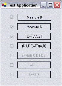
Test application
The test application describes the process represented by Fig. 6.
For illustration purposes, each button corresponds to a certain task. Execution of a task is imitated by button click. Adjacent checkbox indicates the state of a task: performed/not performed, see Fig. 1.
Brief description of the project
The solution accompanying this article consists of 4 projects:
- The project Environment contains all the interfaces and the classes implementing them. This is just a core of the solution.
- The project TestConsole illustrates the simplest way to create a scheme of the project and to run some of the Wizard's commands.
- The project LogicLayer describes a diagram depicted in Fig. 6.
- The project TestWinApplication is a GUI application. It illustrates how a Wizard functions, making use of minimal graphic tools, see Fig. 1.
History
The application was written about a year ago for a few days. I decided that it can be of interest for a wide audience, and hence decided to submit this short article.
MSc in System Engineering from Tallinn Technical University, Estonia. Currently, I work in a hitech enterprise in Israel.


 General
  News
News  Suggestion
  Question
  Bug
Bug  Answer
  Joke
Joke  Praise
  Rant
Rant  Admin
Admin 


