Introduction
This RayTracer is a hobby project of mine. It has some very nice features (such
as reflection and anti-aliasing) but it is not by far finished. This demo application is meant for anyone interested in raytracing, image generation and 3D rendering.
It shows in a straightforward manner how raytracing is done. Although this raytracer
only currently supports just a few shapes (plane, box and sphere). I was aiming
at allowing developers to easily add their own objects/shapes to the scene, which
I will explain later on in this article.
In this article I will shortly explain the basics of raytracing, explain commonly
used terminology
in raytracing and a few of the many raytracing effects that can be achieved
to create a realistic scene. I will explain the algorithms and techniques I used
and explain how this project can be extended with your own shapes, and possible
your own effects.
Note that there are a number of raytracers out there (e.g. the well-known PovRay)
and
even open source raytracers that have more features than this one. I find that the
problem with these raytracers is often that they are hard to understand, either because they are poorly documented, or the algorithms used are optimized for speed, which makes
them practically unreadable - unless if you know what you are
doing. One of the good aspects of this particular raytracer is that it is fully
implemented in C# 2.0, and the code is well documented!
Sources and Demo
The sources project contains all sources of the RayTracer library
and of the demo project. Feel free to use and adapt this code for your own purposes.
The demo project contains the RayTracer library and an example program that has
several predefined scenes. You can select a scene under Tools\Scenes in the menu.
From the settings menu you can turn on/off some of the effects. In the Edit menu
select the Copy function to copy the raytraced image onto the clipboard.
Background
I won't go too much into Raytracing background and history here. There is a lot
to find about raytracing simply by looking on the web. Also I would like to point
out "A raytracer for the
Compact Framework" by gregs here on Code Project that explains some of the
raytracing basics.
For now I will explain some
common concepts used in ray tracing.
Basic raytracing definitions

Figure 1. An example raytracing Scene.
- Camera is defined by its Position in
the Scene (a 3D Vector), a point to LookAt
(the purple arrow) which points at the center of the Viewport, and
the tilt of the Camera (the blue arrow) called Top (it usually
points strait up).
- The Light is defined by its Position in the scene and the
Color of the light denoted by the light bulb.
- The Viewport is derived from the Camera settings and is defined by the LookAt point
of the Camera and a fixed size of (-1,-1)-(1,1).
- A Ray is defined by a starting Position, and a Direction
in which the Ray is casted.
- The Background is defined by a Color that will be displayed if
it is not covered by any other shape.
In a typical raytracing setting a Ray is casted through each pixel in the Viewport
into the Scene, in this example the black arrow. The Raytracer will try and find
out if the Ray is intersecting with any object/shape in the scene. In this example
it will intersect with the Sphere. Otherwise it will simply display the Background
color. To determine the Color to display for the pixel,
a number of techniques can be used and mixed. I call them shading effects.
Shading effects and Color
Because raytracing scenes require usually a high precision of calculations, the
Color as we know it from the Drawing namespace has been replaced by our own RayTracer.Color
definition. Here the R, G and B components are scaled down to a floating point
number between 0 and 1. Also some of the common arithmetic operators have been overridden,
so it will be easier to add, multiply and blend Colors.
The most basic technique is by simply
displaying the intrinsic Color of the Sphere itself. This is called Ambient
lighting. Ambient light is the so
called background light that will light up all objects in the scene slightly (see
figure 2a).
The color is also influenced by the amount of light emitted by surrounding other
light
sources. In this case the light bulb will light up the surface of the sphere depending
on how well the surface is exposed to the light. The yellow arrow shows the direction
in which the light is traced back to its source. Based on this direction, and the
direction the surface of the sphere is facing, the amount of light is calculated.
This is called Diffuse light. It gives a nice shading effect (see
figure 2b).
Additionally the effects can be enhanced by introducing Highlights,
if the surface is somewhat reflective and the rays from the light source are reflected
on the shape's surface strait into the camera, a highlight appears: usually a very shiny and bright
color.
Now for even more effects we can add Reflection and Refraction.
In the case of Reflection, the Ray casted from the Camera is reflected on the surface
of the sphere onto the green box denoted by the red arrow. This means the particular
pixel the Ray travels through will light up with a somewhat greenish color also: the box is
reflected into the sphere.
Refraction is somewhat more complicated. Refraction is the effect of a ray bending
when traveling through a different Material. This applies to transparent objects/shapes.
An example of this is a glass ball, where the light rays are bent when traveling
through the ball.
Then another type of effect we can add to the scene is Shadows.
Shadows do not add Color to a pixel, but instead reduce the amount of Color. To find
out if an intersection with an object is in a shadow of another object, simply trace
the path back to the light source (yellow arrow) and find out of any object is blocking
it (does it intersect with any other object than the light source?).
If it is blocked,
simply reduce the amount of light by a factor.
Figure 2.
Shading effects: a) Ambient, b) Diffuse, c) Highlights, d) Shadows and
e) Reflection (notice the reflection on the floor also)
When rendering a scene containing these basic features (even with just ambient,
diffuse, highlights and shadows), you would already get a quite amazingly raytraced
image, even more so if you built the raytracer from scratch! But of course we are
far from finished.
Texture
One important additional feature is texture. To make any scene look even more realistic
you must be able to add textures to shapes. So how is it done? Basically texture
can be compared to a piece of gift wrapper, which is wrapped around the object. There
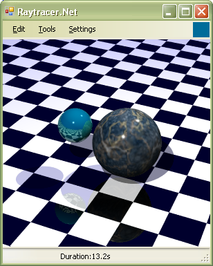
are two types of texture materials: a texture material based on a colormap or image
(e.g. see the marble effect in the top image), and a texture material that
is calculated (e.g. the chessboard
effect).
Textures are flat and therefore require two coordinates to determine the color to
display: often the u and v notation is used. The (u,v) coordinates are mapped onto
(-1,-1)-(1,1) and from there on the color is either read from the colormap, or calculated
respectively. The difficulty lies in calculating the (u,v) coordinates from an intersection
point with the shape. Depending on the shape, the (u,v) coordinates need to be calculated
in different ways, but this is up to that programmer to implement.
Anti-Aliasing
One other important feature to have in a Raytracer is the ability to cope with
Anti-Aliasing. Anti-aliasing is a technique to soften huge color differences
between neighbouring pixels, so it will look more soothing for the eye. Several
techniques can be used to counter this aliasing effect. A quick but dirty technique
is to simply apply a 'mean filter'. The pixel will get the mean color value of neighbouring
pixels. This is implemented as the 'Quick' AntiAliasing method in this raytracer
app. This results is a smoothed image, however the image may also appear a bit
vague/blurry.
A much nicer way of anti-aliasing is using the 'Monte-carlo' method. The idea here
is instead of casting a single ray into the scene through a pixel on the viewport,
instead we cast multiple rays through a single pixel, scanning the neighbourhood
and taking the average color of those. Although the method is slower, since we are now casting multiple rays for a single
pixel, the accuracy is much better, resulting in much smoother but sharp Anti-Aliased images
as shown in the figure below.
Figure 3. AntiAliasing methods: a) None, b) Mean filter, c) Monte Carlo sampling
(using a Very High sampling rate of 64 rays for a single pixel)
Shapes
Apart from cool shading effects more importantly it is to have well defined objects
that make up your scene. Because the term 'object' is a bit overused, I prefer to
use the term Shape when referring to an object in a Scene.
Have you ever wondered why in every raytraced image you always see a lot of spheres?
Well apart from the nice shading effects on a sphere, more importantly, the intersection
of a ray with a sphere can be calculated very fast. This is probably the most important
aspect of a shape definition: how easy is it to calculate the intersection with
the shape. Secondary to that, how easy is it to calculate its surface normal vector.
Calculating the intersection of a ray with arbitrary shapes turns out to be rather
difficult. Instead different methods have been invented such as Voxel techniques
or Marching cubes in order to determine the intersection points.
The most successful approach so far is to create a so called Mesh to describe the
shape. A mesh is created by sampling the shape into small linked triangles. This
process is also known as tessellation. The advantage of using triangles in this case,
is because the intersection of a ray with a triangle is not hard to calculate and
can be done rather efficiently as well. A disadvantage is that in order to create
a smooth mesh, it is required to sample a whole lot of triangles. This means that
the intersection calculation will also need to be executed more often, potentially
killing the performance of the raytracer.
This Raytracer however has not been optimized much for performance, and therefore
only supports a limited set of shapes: Plane, Sphere (of course) and a Box. A small
side note I would like to make here, is that the algorithm used to calculate the
intersection of a ray with the sphere is the fastest one I could find on the web.
Figure 4. Scene with Box and Sphere.
Using the code
In this topic I will explain the basics of how to use the RayTracer library, and
how to extend it with your own additional shapes and materials.
Building a scene
Before we can actually start the raytracing process, we first need to setup a scene.
Right now a scene can only be setup programmatically. Of course you are invited to
change the code in such a way that the scene can be loaded for instance from a file.
So how does one setup a scene programmatically? As stated in the previous section,
we need a Camera, some Background, some Shapes and possible one or more Lights to
light the scene. Setting up a Shape has one catch though, we will need to supply a
Material for the Shape. Currently we have three types of materials: Solid, Texture and
Chessboard. Each material can have additional parameters to specify: gloss (also
known as shininess, or how well is the shape highlighted), reflection (how reflective
is the shape), transparency (how transparent is the shape), refraction (how well
is the light bent when traveling through the shape, in case of transparent shapes).
To give an example see the code below. It will create a scene as shown in the first
image on this page (Scene1 in the code).
Scene scene = new Scene();
scene.Camera = new Camera(new Vector(0, 0, -15), new Vector(-.2, 0, 5),
new Vector(0, 1, 0));
scene.Background = new Background(new Color(0, 0, .5), 0.2);
scene.Shapes.Add(new SphereShape(new Vector(-1.5, 0.5, 0), .5,
new SolidMaterial(new Color(0, .5, .5), 0.2, 0.0, 2.0)));
Texture marbleTexture = Texture.FromFile(path + @"\marble1.png");
TextureMaterial marbleMaterial = new TextureMaterial(marbleTexture, 0.0,
0.0, 2, .5);
scene.Shapes.Add(new SphereShape(new Vector(0, 0, 0), 1, marbleMaterial));
scene.Shapes.Add(new PlaneShape(new Vector(0.1, 0.9, -0.5).Normalize(), 1.2,
new ChessboardMaterial(new Color(1, 1, 1),
new Color(0, 0, 0), 0.2, 0, 1, 0.7)));
scene.Lights.Add(new Light(new Vector(5, 10, -1), new Color(0.8, 0.8, 0.8)));
scene.Lights.Add(new Light(new Vector(-3, 5, -15), new Color(0.8, 0.8, 0.8)));
Raytracing a scene
Now that we have created a scene, we can start RayTracing it! The following code
shows how it is done:
RayTracer.RayTracer tracer = new RayTracer.RayTracer();
Drawing.Rectangle rect = new Drawing.Rectangle(0, 0, 300, 300);
Bitmap bitmap = new Drawing.Bitmap(rect.Width, rect.Height);
Drawing.Graphics g = Drawing.Graphics.FromImage(bitmap);
raytracer.RayTraceScene(g, rect, scene);
After executing the previous two blocks of code, you should be able to get the
same nicely rendered image as on the top of this page.
Another available scene in RayTracer.Net is the following figure:
Figure 5: Another example.
Extending the RayTracer library: Shapes
Basically this library has two main extension points available: for the Shapes and
for the Materials. Each Shape must implement the IShape interface. If you plan to
add your own shape (e.g. a triangle, or mesh) you must implement the IShape interface.
However I made it easy for you. You can derive your new shape class from the BaseShape
class. This class implements the default tedious properties and methods of IShape for you.
However one method you must always implement, which is the Intersect method. This is probably the hardest to implement, but well, there you have it.
The Intersect method expects a Ray and returns an IntersectionInfo object. This
IntersectionInfo object contains all the raytracer needs to know about the intersection
and how to render the color. If the Ray intersects with your shape you must set
the following properties of the IntersectInfo object:
IsHit = true, this indicates that an intersection of the Ray with the Shape has occurred. Distance, this denotes the distance of the starting point of the Ray to the point
of intersection.Position, this is the point of intersection with the object.Normal, this is the normal vector in the direction the surface is facing at the
point of intersection.Color, this is the color at the point of intersection (the color may change depending
if the shape has a texture material applied).
This is all the information the RayTracer needs to successfully render the shape.
Extending the RayTracer library: Materials
If you are not happy with the currently available materials, e.g. if you want to
create a material that supports display of text, you can create your own material.
Each material must implement the IMaterial interface. However again, to make life
easy I have implemented a BaseMaterial class that implements most of the properties
and methods for you. So all you have to do is create a new material
class and derive
it from BaseMaterial.
There is one property and one method you will need to implement for your own material:
HasTexture and GetColor respectively.
HasTexture indicates whether the material supports some kind of texturing. If this
is the case, correct (u,v) coordinates are to be supplied when calling the
GetColor
method. So most probably for your material you are to implement the property to
always return True. GetColor, this method is supplied with the (u,v) coordinates, so the GetColor method
can determine what color to return based on these coordinates. Note that (u,v) will
always be (0,0) if the HasTexture property == false. This is implemented for performance,
calculating exact (u,v) coordinates requires additional calculations depending on
the shape.
Note that the supplied (u,v) coordinates are not restricted. So if you require the
(u,v) coordinates to be mapped onto a texture for instance, you will need to write
your own projection of these (u,v) coordinates onto the texture coordinates.
The BaseMaterial has implemented a helper function for this called:WrapUp, this function will modulate a floating point number onto the a value between
[-1,1]. e.g. a value of -1.1 will be mapped to 0.9. but a value of -2.1 will be
mapped to -0.1! (take a look at the implementation if it is not clear).
So when you have implemented HasTexture and GetColor attributes, you are ready to
use the material in a scene.
Points of Interest
So far we have ambient, diffuse, highlights, shadows, reflection, refraction, textures. So,
are we done yet? The answer to this question is both yes and no. This particular
Raytracer example implementation will not go beyond these effects. (Un)fortunately
there are many more possible effects to add realism to the scene, for example:
- Soft shadows
- Bumpmapping
- Directed lighting
- Light emitting objects
- Particles
- Photon mapping
- Meshes
- Perlin noise texture generators, e.g to create a marble or wood textures.
- Water/Fire like textures/algorithms
- Toon shading for a cartoon like effect
- And a whole lot more that I forgot...
But the most important feature to consider is Performance. Speed is and has always been the
biggest issue so far for raytracers. In order to render realistic scenes within
a limited timeframe will require a number of optimizations:
- Use standard render libraries, e.g. OpenGL or DirectX
- Code optimizations
- Caching and other memory optimizations
- Algorithm optimizations
- Use of KD-trees
- Possible hardware optimizations, check out articles on real-time raytracing.
If you are interested on reading up more about this raytracing stuff it may be worth
your while to check out the following very good reference sites of which I got most
of my information to build this raytracer:
History
Version 1.0 of the RayTracer.Net was publishes on the 11th of October 2006.
Currently Herre Kuijpers is employed at Rubicon. During his career he developed skills with all kinds of technologies, methodologies and programming languages such as c#, ASP.Net, .Net Core, VC++, Javascript, SQL, Agile, Scrum, DevOps, ALM. Currently he fulfills the role of software architect in various projects.
Herre Kuijpers is a very experienced software architect with deep knowledge of software design and development on the Microsoft .Net platform. He has a broad knowledge of Microsoft products and knows how these, in combination with custom software, can be optimally implemented in the often complex environment of the customer.


 General
  News
News  Suggestion
  Question
  Bug
Bug  Answer
  Joke
Joke  Praise
  Rant
Rant  Admin
Admin 


