Introduction
You can consider this as the second episode to the first article Drawing nearly perfect 2D line segments in OpenGL. In a 2D graphics application, drawing only line segments is not enough. We need polylines.
Analysis
 Why don't we draw a polyline by a set of line segments?
If we do so, there would be a gap and overdraw at the join between segments. The image on the right is 2 grey segments with 50% transparency. There is a big gap and the darkened part is drawn 2 times. Any polyline thicker than 1.5px will not look good.
To avoid gaps and overdraw (pretend this word is a noun), proper joint treatment is needed. The 3 common joint types as seen in Cairo and most graphics libraries are:
- miter
 Get the 'outer' border of each line segment and find the intersection point. Use the intersection point as the sharp end. However when the angle between lines is really small, intersection point would be at infinity. As a fall back when the included angle is smaller than a critical value, switch to type bevel.
This not a perfect solution, as, if the polyline is animatable, it would change abruptly from sharp to beveled. - bevel
 Take the 'outer' corner of the two lines and connect them to form a bevel.
 - round
 Draw a circle centered at the common vertex with radius half the line width. Sounds easy but if not drawn carefully, there would be serious overdraw.
and common cap types:
- butt
 The red line is the skeleton of the segment and a butt end always stays inside it.
 - round
 Draw a semi- circle, with radius half the line width, at the end points of a segment.
 - square
 Visually it is the same as a butt end. A segment is extended at a 'square cap', where the extension is equal to half the line width.
Our Approach

Any polyline can be broken down into a set of 3-points-polyline ('^' or 'v'), and we call them anchors. In other words, base on an anchor drawing routine, we can build a polyline drawing routine easily.
Note: the approach attempted in this article is not general polygon outward offsetting (as in computational geometry) or line buffering (as in GIS). Readers should seek other resources for those approaches.
The workflow to draw a polyline by tessellation:
- We receive a series of points which make up a polyline, together with color, thickness and additional styles like joint type and cap type
- Break down the polyline into a set of anchors and issue
anchor() calls - Calculate the geometry(outline) of the anchors according to the thickness
- Break down the geometry into triangles with no overlap
- According to the outline, give each vertex of the triangles a color with alpha
- Output the list of triangles and send them off the rendering pipeline, to be rasterized ultimately.
We will go through these steps one by one now, except 6, to keep this article less OpenGL specific.
Input
Assume we receives an array of points and color by:
struct Point
{
double x,y;
};
struct Color
{
float r,g,b,a;
};
void polyline( const Point* P, const Color* C, int size_of_P,
double weight, char joint_type, char cap_type);
And the Point class has many methods and overloaded operators, allowing us to do something like Point mid_point = (P[0]+P[1])*0.5;
We will discover why we are receiving an array of color soon.
Breaking Down a Polyline into Anchors
There are many possible ways to break, and the simplest is to break at the mid point of each segment:

- Find the mid point of each segment of the polyline. The mid point between
P[0] and P[1] is referred as mid[0] - Replace
mid[0] with P[0] and mid[size_of_P-2] with P[size_of_P-1] - For
i=1 to size_of_P-2,
create anchor with points[mid[i-1],P[i],mid[i]]
The first cap of the first anchor and the last cap of the last anchor must be drawn. No cap for rest of the anchors. That means the anchor() function must allow us to choose which cap to draw.
The declaration of anchor() should then be like:
void anchor( const Point* P, const Color* C,
         double weight, char joint_type, char cap_type,
         bool cap_first, bool cap_last);
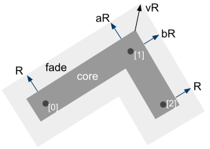
Anchor Metrics
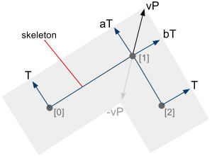
P[0],P[1],P[2] | The 3 points which make up an anchor |
T[0] | The perpendicular vector of the line[P[0],P[1]], pointing from P[0] to the outer border of an anchor |
T[2] | The perpendicular vector of the line[P[1],P[2]], pointing from P[2] to the outer border of an anchor |
aT[1] | Same as T[0] but placed on P[1] |
bT[1] | Same as T[2] but placed on P[1] |
vP[1] | A vector pointing from P[1] to the intersection of
line [T'[0],aT'[1]] and [T'[2],bT'[1]],
with the 4 vectors placed on their respective points, e.g. T'[0]=T[0]+P[0] |
To get the outward vector, rotate the vector T[0]=P[1]-P[0] anti- clockwise 90 degrees. If the points P[0],P[1],P[2] are in clockwise order, do nothing. Otherwise, put the vector T[0] in the opposite direction. Then normalize T[0] and scale to the required thinkness.
Note: All code here uses upper left as origin. Clockwise/ anti- clockwise depends on your chosen coordinate system.
In pseudo- C++ code,
Point T[3];
T[0] = P[1]-P[0]; T[2] = P[2]-P[1];
T[0] = perpen(T[0]); T[2] = perpen(T[2]);
if ( signed_area(P[0],P[1],P[2]) > 0)
{
T[0] = -T[0]; T[2] = -T[2];
}
T[0] = normalize(T[0]); T[2] = normalize(T[2]);
T[0] *= weight; T[2] *= weight;
Point perpen(Point P) {
return Point(-P.y,P.x);
}
double signed_area(Point P1, Point P2, Point P3)
{
return (P2.x-P1.x)*(P3.y-P1.y) - (P3.x-P1.x)*(P2.y-P1.y);
}
To calculate the intersection point between 2 lines, the method is explained here. Say we have an implementation like this:
int intersect( Point P1, Point P2, Point P3, Point P4, Point& Pout); { double mua,mub;
double denom,numera,numerb;
const double eps = 0.000000000001;
denom = (P4.y-P3.y) * (P2.x-P1.x) - (P4.x-P3.x) * (P2.y-P1.y);
numera = (P4.x-P3.x) * (P1.y-P3.y) - (P4.y-P3.y) * (P1.x-P3.x);
numerb = (P2.x-P1.x) * (P1.y-P3.y) - (P2.y-P1.y) * (P1.x-P3.x);
if ( (-eps < numera && numera < eps) &&
(-eps < numerb && numerb < eps) &&
(-eps < denom && denom < eps) ) {
Pout.x = (P1.x + P2.x) * 0.5;
Pout.y = (P1.y + P2.y) * 0.5;
return 2; }
if (-eps < denom && denom < eps) {
Pout.x = 0;
Pout.y = 0;
return 0; }
mua = numera / denom;
mub = numerb / denom;
Pout.x = P1.x + mua * (P2.x - P1.x);
Pout.y = P1.y + mua * (P2.y - P1.y);
bool out1 = mua < 0 || mua > 1;
bool out2 = mub < 0 || mub > 1;
if ( out1 & out2) {
return 5; } else if ( out1) {
return 3; } else if ( out2) {
return 4; } else {
return 1; }
}
Then find vP by:
Point interP, vP;
intersect( T[0]+P[0],T[0]+P[1], T[2]+P[2],T[2]+P[1], interP);
vP = interP - P[1];
Having all these metrics, we can triangulate anchors for mitered joint and bevelled joint without difficulty, but not a round joint.
Inner Arc
As mentioned before, to avoid overdraw, we cannot simply draw a circle over a round joint. We should only fill the gap by creating an inner arc from aT to bT. An inner arc is the shorter one of the 2 possible arcs between 2 specified angles.
First, let's look at the code for a basic arc:
void basic_arc( Point P, float r, float dangle, float angle1, float angle2)
{
bool incremental=true;
if ( angle1>angle2) {
incremental = false; }
if ( incremental) {
for ( float a=angle1; a < angle2; a+=dangle)
{
float x=cos(a); float y=sin(a);
Point q( P.x+x*r,P.y-y*r); }
} else {
for ( float a=angle1; a > angle2; a-=dangle)
{
float x=cos(a); float y=sin(a);
Point q( P.x+x*r,P.y-y*r);
}
}
}
The first trial to fill an arc between 2 vectors:
void basic_vectors_arc( Point P, Point A, Point B,
float r) {
A = normalize(A); B = normalize(B);
float angle1=acos(A.x); float angle2=acos(B.x);
basic_arc( P,r,PI/18, angle1,angle2);
}
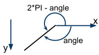
It only gives correct result when both A and B are upward. When any one of them is downward, it is wrong, see the interactive demo. One reason is arc cosine returns only from 0 to PI, i.e., 0 to 180 degrees. To extend the range to 0 to 2*PI, do this after getting the value of acos():
if ( A.y>0){ angle1=2*PI-angle1;}
if ( B.y>0){ angle2=2*PI-angle2;}
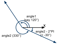
An inner arc is always shorter than or equal to a half- circumference. If angle2-angle1 is greater than PI, minus angle2 by 2*PI.
Consider the image on the left. Say angle1=120° and angle2=330°. If the arc is calculated incrementally from angle1 to angle2, it would be an outer arc. Since angle2-angle1=210° > 180°, minus angle2 by 360° and becomes -30°. As defined by basic_arc, the arc is now calculated incrementally from angle2 to angle1, which is an inner arc. Handle similarly when angle1>angle2.
Sample code is at
the same place.
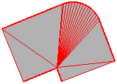
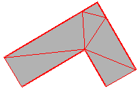
Then, we can generate a triangle fan between aT and bT for round joint and round cap. The triangulation on the left chose -vP as the apparent center of the fan. Anyway, if the color is all the same over an anchor, the form of triangulation does not matter. Otherwise, triangulation does affect color interpolation.
Tips: Use arc length = radius * angle to control dangle, so that the joint would remain smooth under any thickness, as the number of triangles is made proportional to radius.
Applying Colors
We are receiving an array of color because we want to do per- vertex coloring. There are many profiles of coloring, as much as a child can produce by coloring a car with crayons. Here we just give each vertex the color of its nearest input vertex.


Suggested further work in coloring profile.
Facing the Failed Case
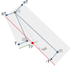
The above mentioned tessellation method can draw an anchor correctly at most cases. But not when the two segments are making a very small angle, overlapping and start to degenerate into one line segment. At degenerated case, the intersection point vP would be at infinity. We now have a slightly differed set of metrics.
To identify a degeneration, intersect the green line segment [T[2]+P[2], -T[2]+P[2]] with the red one [-T[0]+P[1], -T[0]+P[0]]. If the intersection point TP lies inside both segments, degeneration occurs.
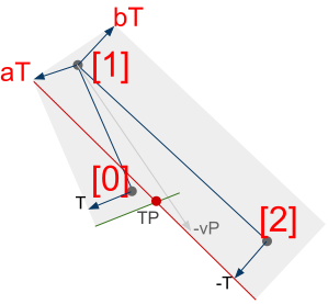
Consider again when the order of points is reversed.
Luckily, the joint is unaffected.
Fade Polygon
To achieve anti-aliasing using the 'fade polygon technique' mentioned in the first article, or just to make it more complicated, we can also render the fade polygon of an anchor. The math is the same, so I will not cover it here.

An addon is we can arbitrary scale the thickness of the fade polygon to achieve feathering. The effect? Very cool!
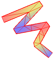
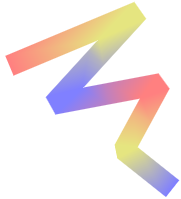
Image on the right: An implementation of anchor() with round joint, round caps and feathering in OpenGL.
Introducing Vase Renderer
The implementation of all the above mentioned ideas to render polylines is put into a library called Vase Renderer. It is open sourced. It is still young so the only function it has is polyline().
Vase Renderer is the attempt to create high quality 2D graphics in OpenGL with a different fundament. Instead of thinking about pixels, we think about triangles. It is the attempt to break historical limitations of 2D graphics libraries. For example, Cairo, SVG has no per vertex color. They do not allow variable color along a polyline. It is not that they cannot think of this feature (I believe), just it takes so much consideration to support varying color that they would better redesign the library from scratch. 2D computer graphics still needs evolution.
The benefit of tessellating each triangle by hand is you can control the color of each vertex, form of each triangle and overall topology. We can then create graceful color blending. Moreover, although the implementation process is tough, once it is finished, the result is nice and fast.
Using the Code
For latest source, usage and issues about Vase Renderer, visit the current documentation page.
Limitations
Each anchor is processed separately and is independent of each other. At degeneration, overdraw would occur. If the polyline is colored, the artifact is especially obvious. At current Vase Renderer implementation, when a segment of a polyline is shorter than its own width, the result will 'go wild'. That means practically we cannot use polyline() to draw a curve where points are dense.
Anyway, these limitations can be overcome by careful (and painful) inspection, in the same way as all the techniques in this article were developed.


And hopefully, the next update of this article will be the solution to them.
Chris H.F. Tsang
tyt2y3@gmail.com


 General
  News
News  Suggestion
  Question
  Bug
Bug  Answer
  Joke
Joke  Praise
  Rant
Rant  Admin
Admin 


 , my 5