Introduction
This technique is an innovative way of generating aesthetic line types. It is useful mainly in CAD/GIS and allied applications where there is a need for customized line types. It is written entirely using MFC and is very simple to use.
Background
I was researching on creating the custom line types. My efforts of generating such line types included:
- Use of Vector drawings to lay down along a given line. It involved complex math using matrices. But it was inefficient and could not be applied for geometrical entities that are filled.
- Use of fractal geometry, which too proved unwise as it required an effort to invent a new formula for every line pattern that I am interested in.
- I came across an article Using LineDDA to Produce Complex Line Styles (codeguru) which involved the use of Callback procedures to draw complex line types. This technique is a Win32 solution and is currently not supported directly by MFC. Although it is a brilliant solution, it was not foolproof and I was getting undesired output. For instance, when I have chosen character “X” as input for line pattern, the outputs are as follows: (Fig 1&2).
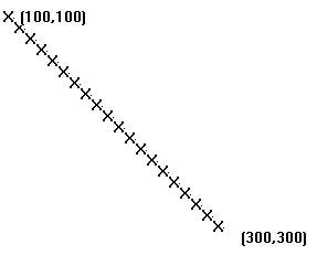 |  |
Fig 1.Desired Output
| Fig 2.Wrong Output
|
This motivated me to work for the solution in MFC that is simpler, elegant and not taxing on the intellect of an average programmer. I have used Truetype (.ttf) fonts to generate line types. Each Glyph (Microsoft typography) in the font can be used as a pattern for the line.
The Technique
Fig 3: Character Maps in Windows
Use Microsoft’s Character Map Application (Start >All Programs > Accessories > System Tools > Character Map) and select a character or symbol (which represents a pattern for your line type) from a desired font. Each symbol has unique hexadecimal number associated with it. We make use of this hexadecimal number in our logic. The symbol highlighted in the above image has a hexadecimal number 0x5C.
Fig 3
Note:-I am planning to extend this application by making use of code in the article XCharMap - A dialog to display a character map by Hans Dietrich in this site.
You may design your own patterns as symbols of a Truetype font using Font creation tools like CorelDraw, Font Creator or Fontlab.Copy the Font you have created into Fonts folder of Windows Directory.
Understanding the Code
I have adopted the code for drawing the Rubberband line from Chapter3 of Jeff Prosise’s ‘Programming Windows with MFC’, which I am not explaining here. The core logic is in OnLButtonUp of view class.
To arrange a desired pattern along the line drawn, first, compute the slope of the line and angle subtended by the line w.r.t horizontal.
if(point.x-m_ptFrom.x==0)
return;
float slope= -(point.y
-m_ptFrom.y)/(point.x-m_ptFrom.x);
in clockwise direction , while the direction.
horizontal
float ang=atan2(m_ptFrom.y-point.y,point.x-m_ptFrom.x)*180.0f/3.1415927f;
Assign the angle to the Orientation and Escapement properties of LOGFONT variable. Select the Font of interest and assign the Hexadecimal value of the character/symbol to a CString variable.
LOGFONT lf;
lf.lfCharSet=SYMBOL_CHARSET;lf.lfHeight=20;
lf.lfEscapement=(long)ang*10;lf.lfOrientation=(long)ang*10;lf.lfItalic=false;
lf.lfStrikeOut=false;
lf.lfUnderline=false;
lf.lfQuality=ANTIALIASED_QUALITY;
lf.lfWeight=FW_BOLD;
strcpy(lf.lfFaceName,_T("Wingdings"));
--
--
--
--
--
--
CString str;
str=0x5c;
Find length of the line segment and repeatedly add the hexadecimal value of the character/symbol to the CString variable until the width of string is less than length of line. Draw the text and we get our amazing line patterns.
float dist= sqrt( (point.y - m_ptFrom.y )*(point.y-m_ptFrom.y)+
(point.x-m_ptFrom.x)*(point.x-m_ptFrom.x) ) ;
while(textwidth < dist )
{
str+=0x5c;
textwidth=dc.GetTextExtent(str).cx;
}
Running the Application
Compile and build it in VS6. Click and drag to draw a Rubberband line.
Observe that, if the drawing from source point to destination draws the text below the line, while drawing from destination to source draws the text above the line. We get the inverted symbol by just reversing the order of drawing.
Fig 6
Fig 4: Line Patterns Generated
Further Improvement
- Selection of desired symbol from a Character Map Dialog box invoked from within this application. (Let me contact Hans Dietrich on that).
- Extend the drawing logic for enabling user to draw polylines and polygons.
- Provide a Dialog box for selecting Font size, color, alignment etc.
References
Acknowledgements
Pravin Ramdas Raijade
He works in the GIS and allied technologies. His areas of Interest are GIS/CAD ,Defence,Aerospace and Law Enforcement.


