Introduction
This is the second tutorial of the Writing Device Drivers series. There seems to be a lot of interest in the topic, so this article will pick up where the first left off. The main focus of these articles will be to build up little by little the knowledge needed to write device drivers. In this article, we will be building on the same example source code used in part one. In this article, we will expand on that code to include Read functionality, Handle Input/Ouput Controls also known as IOCTLs, and learn a bit more about IRPs.
F.A.Q.
Before we begin with this article, here is a small list of some frequently asked questions that we can clear up.
Where do I get the DDK?
Microsoft allows MSDN subscribers to download the DDK from their website. If you do not subscribe, they sometimes allow new DDKs to be openly downloaded by the public for a certain period of time. At the time of this article, no DDKs are available for download, so if you are not a subscriber, you can request they mail you the DDK CD for the cost of shipping and handling. You can order the DDK from here.
Can I include windows.h in my driver?
You cannot mix the Windows SDK header files with the Windows DDK header files. They have definitions that will conflict and you will have trouble getting the code to compile. Sometimes there are user-mode applications which like to include part of the DDK. These generally will have to take out the types they want to define from the DDK or SDK and put them directly in their file. The other popular approach used where possible is to separate the files into DDK and SDK usage so each .C can include the appropriate headers without conflict.
Can I implement “x” type driver like this?
This is the general generic framework for which mostly all drivers are built upon in Windows. Drivers do not have to implement hardware, and as mentioned in the first tutorial, there is usually a stack of drivers. If you are looking to implement a specific type of driver, this is a starting point to understand in general how drivers work. The difference then becomes how you advertise your device to the system, what IOCTLs you implement, what drivers you communicate to underneath your driver, and any additional pieces you are required to implement such as supporting drivers or even user mode components. If you are looking to implement a specific type of driver, you will want to read information specific to that driver on MSDN, in the DDK and other places. There are sometimes other frameworks which actually encapsulate most of what we are doing here so it’s easier to write for example.
Can I use the C or C++ runtime in a driver?
You should avoid using these in a driver and instead use the equivalent kernel mode APIs. Kernel Run Time Library also includes a subtopic on Safe String Functions. When programming in the kernel, there are some pitfalls you may need to be aware of, and if you never look up the real kernel API, you may never be aware of these since you would never have read the "remarks" section for example. The kernel APIs also tell you at what IRQL you can use each of the functions. It is a lot safer and in your best interest to avoid the standard run time as it will save you time from tracking down bugs and making simple common mistakes in your code.
Implementing the ReadFile
The first article left this as homework so even if you have not completed your homework, here are the answers. There are three types of I/O as we discussed previously and these are Direct, Buffered and Neither. I have implemented all three of these in the example driver. The difference is that instead of reading the memory, we write to the memory. I will not explain all three types of I/O as they are identical. What I will explain is the new functionality that I have added: return values!
In the WriteFile implementation, we didn’t need to worry about the return value. Proper implementations should always inform the user mode application how much data was “written”, however, I omitted this detail for simplicity at the time. This will become essential with the “ReadFile” implementation if not only for properly informing the user mode application but to let the I/O Manager know as well.
If you recall how “Buffered I/O” works for example, the memory buffer is created in another location and the user mode memory is copied. If we want to read data from the driver, the I/O manager needs to know how much memory to copy from this temporary buffer to the real user mode memory location! If we don’t do this, no memory will be copied and the user mode application will not get any data!
NTSTATUS Example_ReadDirectIO(PDEVICE_OBJECT DeviceObject, PIRP Irp)
{
NTSTATUS NtStatus = STATUS_BUFFER_TOO_SMALL;
PIO_STACK_LOCATION pIoStackIrp = NULL;
PCHAR pReturnData = "Example_ReadDirectIO - Hello from the Kernel!";
UINT dwDataSize = sizeof("Example_ReadDirectIO - Hello from the Kernel!");
UINT dwDataRead = 0;
PCHAR pReadDataBuffer;
DbgPrint("Example_ReadDirectIO Called \r\n");
pIoStackIrp = IoGetCurrentIrpStackLocation(Irp);
if(pIoStackIrp && Irp->MdlAddress)
{
pReadDataBuffer = MmGetSystemAddressForMdlSafe(Irp->MdlAddress,
NormalPagePriority);
if(pReadDataBuffer &&
pIoStackIrp->Parameters.Read.Length >= dwDataSize)
{
RtlCopyMemory(pReadDataBuffer, pReturnData,
dwDataSize);
dwDataRead = dwDataSize;
NtStatus = STATUS_SUCCESS;
}
}
Implementing Return Values
The return value is implemented using the IO_STATUS_BLOCK of the IRP. This contains a few data members which vary their use depending on the major function being implemented. In the major functions we are implementing, “Status” is equal to the return code and “Information” contains the number of bytes read or written. Looking at the new code, you also notice that we are now calling “IoCompleteRequest”. What does this all mean?
The IoCompleteRequest is always called by the driver after it completes the IRP. The reason we weren’t doing this in the previous example is that the I/O Manager being a nice guy will in most cases complete this for us. However, it is proper for the driver to complete the IRP where necessary. This location contains a document on “IRP Handling” which can supply more information.
    Irp->IoStatus.Status = NtStatus;
    Irp->IoStatus.Information = dwDataRead;

    IoCompleteRequest(Irp, IO_NO_INCREMENT);

    return NtStatus;
}
The second parameter of the IoCompleteRequest specifies the priority boost to give the thread waiting for this IRP to complete. As an example, perhaps the thread has been waiting a long time for a network operation. This boost helps the scheduler re-run this thread sooner than it may have if it simply went back into the ready queue without a boost. To put this quite simply, it's basically a helper being used to inform the scheduler to re-run the thread waiting for this I/O.
Stricter Parameter Validation and Error Checking
The code now implements a little more error checking and parameter validation than it previously did. This is one thing that you want to make sure with your driver, that a user mode application shouldn’t be able to send invalid memory locations, etc. to the driver and blue screen the system. The driver implementation should also do a little better on the errors it returns to the user mode driver instead of just “STATUS_SUCCESS” all the time. We need to inform the user mode process if it needs to send us more data or attempt to determine exactly when wrong. You like APIs which you can call GetLastError to see why they failed or use the return value to determine how to fix your code. If your driver simply returns “failed” or even better “success” all the time, it becomes harder to know how to make your application work properly with the driver.
Input/Output Controls (IOCTL)
The IOCTL is used as more of a communication between the driver and application rather than simply reading or writing data. Generally, the driver exports a number of IOCTLs and defines data structures that would be used in this communication. Generally, these data structures should not contain pointers since the I/O Manager cannot interpret these structures. All data should be contained in the same block. If you want to create pointers, you can do things such as create offsets into the block of data past the end of the static data so the driver can easily find this information. If you do remember however, the driver does have the ability to read user mode data as long as it’s in the context of the process. So, it is possible to implement pointers to memory and the driver would need to copy the pages or lock the pages in memory (implement basically buffered or direct I/O from within the driver itself, which can be done). The user mode process will use the “DeviceIoControl” API to perform this communication.
Defining the IOCTL
The first thing we need to do is define the IOCTL code to be used between the application and the driver. I will essentially be summarizing this article on MSDN here. First, to relate the IOCTL to something in user mode, you may think of it as a Windows Message. It’s simply a value used by the driver to implement some requested function with predefined input and output values. There is a little more to this value than a Windows Message however. The IOCTL defines the access required in order to issue the IOCTL as well as the method to be used when transferring the data between the driver and the application.
The IOCTL is a 32 bit number. The first two low bits define the “transfer type” which can be METHOD_OUT_DIRECT, METHOD_IN_DIRECT, METHOD_BUFFERED or METHOD_NEITHER.
The next set of bits from 2 to 13 define the “Function Code”. The high bit is referred to as the “custom bit”. This is used to determine user-defined IOCTLs versus system defined. This means that function codes 0x800 and greater are custom defined similar to how WM_USER works for Windows Messages.
The next two bits define the access required to issue the IOCTL. This is how the I/O Manager can reject IOCTL requests if the handle has not been opened with the correct access. The access types are such as FILE_READ_DATA and FILE_WRITE_DATA for example.
The last bits represent the device type the IOCTLs are written for. The high bit again represents user defined values.
There is a macro we can use to define our IOCTLs quickly and it is “CTL_CODE”. I have used it in “public.h” to define four IOCTLs which implement different types of access transfer methods.
#define IOCTL_EXAMPLE_SAMPLE_DIRECT_IN_IO \
CTL_CODE(FILE_DEVICE_UNKNOWN, \
0x800, \
METHOD_IN_DIRECT, \
FILE_READ_DATA | FILE_WRITE_DATA)
#define IOCTL_EXAMPLE_SAMPLE_DIRECT_OUT_IO \
CTL_CODE(FILE_DEVICE_UNKNOWN, \
0x801, \
METHOD_OUT_DIRECT, \
FILE_READ_DATA | FILE_WRITE_DATA)
#define IOCTL_EXAMPLE_SAMPLE_BUFFERED_IO \
CTL_CODE(FILE_DEVICE_UNKNOWN, \
0x802, \
METHOD_BUFFERED, \
FILE_READ_DATA | FILE_WRITE_DATA)
#define IOCTL_EXAMPLE_SAMPLE_NEITHER_IO \
CTL_CODE(FILE_DEVICE_UNKNOWN, \
0x803, \
METHOD_NEITHER, \
FILE_READ_DATA | FILE_WRITE_DATA)
The above displays how we defined our IOCTLs.
Implementing the IOCTL
The first thing that simply needs to occur is essentially a switch statement which distributes the IOCTL to the appropriate implementation. This is essentially the same thing a Windows procedure does to dispatch Windows messages. There is no such thing as a "def IOCTL proc" though!
The "Parameters.DeviceIoControl.IoControlCode" of the IO_STACK_LOCATION contains the IOCTL code being invoked. The following code is essentially a switch statement which dispatches each IOCTL to its implementation.
NTSTATUS Example_IoControl(PDEVICE_OBJECT DeviceObject, PIRP Irp)
{
NTSTATUS NtStatus = STATUS_NOT_SUPPORTED;
PIO_STACK_LOCATION pIoStackIrp = NULL;
UINT dwDataWritten = 0;
DbgPrint("Example_IoControl Called \r\n");
pIoStackIrp = IoGetCurrentIrpStackLocation(Irp);
if(pIoStackIrp)
{
switch(pIoStackIrp->Parameters.DeviceIoControl.IoControlCode)
{
case IOCTL_EXAMPLE_SAMPLE_DIRECT_IN_IO:
NtStatus = Example_HandleSampleIoctl_DirectInIo(Irp,
pIoStackIrp, &dwDataWritten);
break;
case IOCTL_EXAMPLE_SAMPLE_DIRECT_OUT_IO:
NtStatus = Example_HandleSampleIoctl_DirectOutIo(Irp,
pIoStackIrp, &dwDataWritten);
break;
case IOCTL_EXAMPLE_SAMPLE_BUFFERED_IO:
NtStatus = Example_HandleSampleIoctl_BufferedIo(Irp,
pIoStackIrp, &dwDataWritten);
break;
case IOCTL_EXAMPLE_SAMPLE_NEITHER_IO:
NtStatus = Example_HandleSampleIoctl_NeitherIo(Irp,
pIoStackIrp, &dwDataWritten);
break;
}
}
Irp->IoStatus.Status = NtStatus;
Irp->IoStatus.Information = dwDataWritten;
IoCompleteRequest(Irp, IO_NO_INCREMENT);
return NtStatus;
}
If you understand the ReadFile and WriteFile implementations, these simply implement both in one call. This obviously doesn't have to be the case, IOCTLs can be used to only read data, only write data, or not send any data at all but simply inform or instruct the driver to perform an action.
METHOD_x_DIRECT
The METHOD_IN_DIRECT and METHOD_OUT_DIRECT can essentially be explained at the same time. They are basically the same. The INPUT buffer is passed in using "BUFFERED" implementation. The output buffer is passed in using the MdlAddress as explained in the Read/Write implementations. The difference between "IN" and "OUT" is that with "IN", you can use the output buffer to pass in data! The "OUT" is only used to return data. The driver example we have doesn't use the "IN" implementation to pass in data, and essentially the "OUT" and "IN" implementations are the same in the example. Since this is the case, I will just show you the "OUT" implementation.
NTSTATUS Example_HandleSampleIoctl_DirectOutIo(PIRP Irp,
PIO_STACK_LOCATION pIoStackIrp, UINT *pdwDataWritten)
{
NTSTATUS NtStatus = STATUS_UNSUCCESSFUL;
PCHAR pInputBuffer;
PCHAR pOutputBuffer;
UINT dwDataRead = 0, dwDataWritten = 0;
PCHAR pReturnData = "IOCTL - Direct Out I/O From Kernel!";
UINT dwDataSize = sizeof("IOCTL - Direct Out I/O From Kernel!");
DbgPrint("Example_HandleSampleIoctl_DirectOutIo Called \r\n");
pInputBuffer = Irp->AssociatedIrp.SystemBuffer;
pOutputBuffer = NULL;
if(Irp->MdlAddress)
{
pOutputBuffer =
MmGetSystemAddressForMdlSafe(Irp->MdlAddress,
NormalPagePriority);
}
if(pInputBuffer && pOutputBuffer)
{
if(Example_IsStringTerminated(pInputBuffer,
pIoStackIrp->Parameters.DeviceIoControl.InputBufferLength,
&dwDataRead)) {
DbgPrint("UserModeMessage = '%s'", pInputBuffer);
DbgPrint("%i >= %i",
pIoStackIrp->Parameters.DeviceIoControl.OutputBufferLength,
dwDataSize);
if(pIoStackIrp->
Parameters.DeviceIoControl.OutputBufferLength >= dwDataSize)
{
RtlCopyMemory(pOutputBuffer, pReturnData, dwDataSize);
*pdwDataWritten = dwDataSize;
NtStatus = STATUS_SUCCESS;
}
else
{
*pdwDataWritten = dwDataSize;
NtStatus = STATUS_BUFFER_TOO_SMALL;
}
}
}
return NtStatus;
}
As homework, see if you can change the "IN" method to work correctly. Pass input data through the output buffer and display it.
METHOD_BUFFERED
The METHOD_BUFFERED implementation does essentially the same thing as the Read and Write implementations. A buffer is allocated and the data is copied from this buffer. The buffer is created as the larger of the two sizes, the input or output buffer. Then the read buffer is copied to this new buffer. Before you return, you simply copy the return data into the same buffer. The return value is put into the IO_STATUS_BLOCK and the I/O Manager copies the data into the output buffer.
NTSTATUS Example_HandleSampleIoctl_BufferedIo(PIRP Irp,
PIO_STACK_LOCATION pIoStackIrp, UINT *pdwDataWritten)
{
NTSTATUS NtStatus = STATUS_UNSUCCESSFUL;
PCHAR pInputBuffer;
PCHAR pOutputBuffer;
UINT dwDataRead = 0, dwDataWritten = 0;
PCHAR pReturnData = "IOCTL - Buffered I/O From Kernel!";
UINT dwDataSize = sizeof("IOCTL - Buffered I/O From Kernel!");
DbgPrint("Example_HandleSampleIoctl_BufferedIo Called \r\n");
pInputBuffer = Irp->AssociatedIrp.SystemBuffer;
pOutputBuffer = Irp->AssociatedIrp.SystemBuffer;
if(pInputBuffer && pOutputBuffer)
{
if(Example_IsStringTerminated(pInputBuffer,
pIoStackIrp->Parameters.DeviceIoControl.InputBufferLength,
&dwDataRead)) {
DbgPrint("UserModeMessage = '%s'", pInputBuffer);
DbgPrint("%i >= %i",
pIoStackIrp->Parameters.DeviceIoControl.OutputBufferLength,
dwDataSize);
if(pIoStackIrp->Parameters.DeviceIoControl.OutputBufferLength
>= dwDataSize)
{
RtlCopyMemory(pOutputBuffer, pReturnData, dwDataSize);
*pdwDataWritten = dwDataSize;
NtStatus = STATUS_SUCCESS;
}
else
{
*pdwDataWritten = dwDataSize;
NtStatus = STATUS_BUFFER_TOO_SMALL;
}
}
}
return NtStatus;
}
METHOD_NEITHER
This is also the same as implementing neither I/O. The original user mode buffers are passed into the driver.
NTSTATUS Example_HandleSampleIoctl_NeitherIo(PIRP Irp,
PIO_STACK_LOCATION pIoStackIrp, UINT *pdwDataWritten)
{
NTSTATUS NtStatus = STATUS_UNSUCCESSFUL;
PCHAR pInputBuffer;
PCHAR pOutputBuffer;
UINT dwDataRead = 0, dwDataWritten = 0;
PCHAR pReturnData = "IOCTL - Neither I/O From Kernel!";
UINT dwDataSize = sizeof("IOCTL - Neither I/O From Kernel!");
DbgPrint("Example_HandleSampleIoctl_NeitherIo Called \r\n");
pInputBuffer = pIoStackIrp->Parameters.DeviceIoControl.Type3InputBuffer;
pOutputBuffer = Irp->UserBuffer;
if(pInputBuffer && pOutputBuffer)
{
__try {
ProbeForRead(pInputBuffer,
pIoStackIrp->Parameters.DeviceIoControl.InputBufferLength,
TYPE_ALIGNMENT(char));
if(Example_IsStringTerminated(pInputBuffer,
pIoStackIrp->Parameters.DeviceIoControl.InputBufferLength,
&dwDataRead))
{
DbgPrint("UserModeMessage = '%s'", pInputBuffer);
ProbeForWrite(pOutputBuffer,
pIoStackIrp->Parameters.DeviceIoControl.OutputBufferLength,
TYPE_ALIGNMENT(char));
if(pIoStackIrp->
Parameters.DeviceIoControl.OutputBufferLength
>= dwDataSize)
{
RtlCopyMemory(pOutputBuffer,
pReturnData,
dwDataSize);
*pdwDataWritten = dwDataSize;
NtStatus = STATUS_SUCCESS;
}
else
{
*pdwDataWritten = dwDataSize;
NtStatus = STATUS_BUFFER_TOO_SMALL;
}
}
} __except( EXCEPTION_EXECUTE_HANDLER ) {
NtStatus = GetExceptionCode();
}
}
return NtStatus;
}
Calling DeviceIoControl
This is a very simple implementation.
ZeroMemory(szTemp, sizeof(szTemp));
DeviceIoControl(hFile,
                IOCTL_EXAMPLE_SAMPLE_DIRECT_IN_IO,
                "** Hello from User Mode Direct IN I/O",
                sizeof("** Hello from User Mode Direct IN I/O"),
                szTemp,
                sizeof(szTemp),
                &dwReturn,
                NULL);
printf(szTemp);
printf("\n");

ZeroMemory(szTemp, sizeof(szTemp));
DeviceIoControl(hFile,
                 IOCTL_EXAMPLE_SAMPLE_DIRECT_OUT_IO,
                 "** Hello from User Mode Direct OUT I/O",
                 sizeof("** Hello from User Mode Direct OUT I/O"),
                 szTemp,
                 sizeof(szTemp),
                 &dwReturn,
                 NULL);
printf(szTemp);
printf("\n");

ZeroMemory(szTemp, sizeof(szTemp));
DeviceIoControl(hFile,
                IOCTL_EXAMPLE_SAMPLE_BUFFERED_IO,
                "** Hello from User Mode Buffered I/O",
                sizeof("** Hello from User Mode Buffered I/O"),
                szTemp,
                sizeof(szTemp),
                &dwReturn,
                NULL);
printf(szTemp);
printf("\n");

ZeroMemory(szTemp, sizeof(szTemp));
DeviceIoControl(hFile,
                IOCTL_EXAMPLE_SAMPLE_NEITHER_IO,
                "** Hello from User Mode Neither I/O",
                sizeof("** Hello from User Mode Neither I/O"),
                szTemp,
                sizeof(szTemp),
                &dwReturn,
                NULL);
printf(szTemp);
printf("\n");
System Memory Layout
This is probably a good time to look at how Windows memory layout looks. To show how this works, we need to first show how Intel processors implement Virtual Memory. I will explain the general implementation as there are a few variations of how this can be implemented. This is basically called the “Virtual Address Translation”. The following is an excerpt from another document that I have been writing on debugging.
Virtual Address Translation
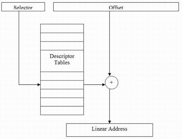
All segment registers become “selectors” in protected mode. To get more familiar with how the x86 operates, we will go over the paging mechanism as an overview and not in detail. This is not a systems programming guide.
There are other registers in the CPU which point to “descriptor tables”. These tables define certain system attributes which we will not go into detail. Instead, we will discuss the process of converting a “virtual” address into a physical address. The descriptor table can define an offset which is then added to the virtual address. If paging is not enabled, once you add these two addresses, you get the physical address. If paging is enabled, you get instead a “linear” address which is then converted to a physical address using page tables.
There is a paging mechanism that is called “Page Address Extensions” which was originally introduced in the Pentium Pro. This mechanism allows Page Tables to reference up to 36 bit addresses. However, offsets are still 32 bit, so while you can access Physical Ram up to 36 bits, you can only access 4 GB at a time without reloading the page tables. This paging mechanism is not what we will be discussing here, but it is very similar.

The normal 32 bit paging is done using the following. There is a CPU register that points to the base of the Page Directory Table, called CR3. The diagram below displays how the paging mechanism works. Notice that the location of the physical page does not need to be linear with the virtual address or even with the previous page table entry. The blue lines are involved in the example translation and the black lines are further examples of how the page tables could be setup.
The “Page Directory Table” has entries which each point to a structure of “Page Table Entries”. The entries in the “Page Table Entry” point to the beginning of a page in the physical RAM. While Windows and most other Operating Systems use 4k pages, the CPU actually can support 4k and 2MB pages.
The entire process can be listed in the following steps if the pages are defined as 4k.
- The selector points to the Descriptor Table Entry.
- The Descript Table Entry “base offset” is added to the offset of the virtual address creating a linear address.
- Bits 31-22 of the Linear Address index into the “Page Directory Table” pointed to by CR3.
- The entry in the “Page Directory Table” points to the base of a “Page Entry Table” which is then indexed by the bits 21 – 12 indexed into this table to retrieve a “Page Table Entry”.
- The “Page Table Entry” aside from containing information about whether the address is paged to disk points to the base location of the page in Physical Memory.
- The remaining bits of the Linear Address, bits 11 – 0 are added to the start of the physical page to create the final physical address.
Windows Implementation
If you generally ignore the implementation of the descriptor tables, the address translation should be quite simple to follow. The address is just divided into sections which help index into memory tables that eventually point to the location of a physical page. The last index simply indexes into that physical page.
Windows implements essentially three separate layers of virtual address ranges. The first would be the user-mode addresses. These addresses are essentially unique per-process. That is, each process will have its own memory addresses in this range. Of course, there are optimizations such as different page tables pointing to the same physical memory location in order to share code and not duplicate memory that is essentially static.
The second range of addresses would be those in the session space. If you have used “Fast User Switching” or “Terminal Services”, you know that each user essentially gets their own desktop. There are certain drivers which run in what is called “Session Space” which is memory that is unique per-session. In this memory are things like the display driver, win32k.sys and some printer drivers. This is one reason why Windows does not span sessions, i.e., you cannot do “FindWindow” and see a window on another user’s desktop.
The last is the range of addresses known as “System Space”. This is memory that is shared throughout the entire system and accessible anywhere. This is where our driver lies and where most drivers lie.
So, what happens? Every time a thread is switched, CR3 is reloaded with the appropriate pointer which points to the page tables accessible by that thread. The implementation is that each process has its own page directory pointer and it’s loaded into CR3. This is essentially how Windows isolates each process from one another, they all have their own directory pointer. This directory pointer is implemented in a way that processes in the same session map the same session space, and all processes on the system map system memory. The only memory ranges implemented unique per-process is essentially the user mode address ranges.
The /PAE Switch
This is called "Physical Address Extensions". It basically means the OS can map 36 bit physical memory into 32 bits. This doesn't mean that you can access > 4 GB of memory at the same time, it means that higher memory addresses can be mapped into 32 bits which means the process can access it. This also means that the OS could use this ability to use machines with > 4 GB of physical memory. So while one process may not access > 4 GB, the OS can manage the memory in a way that it can keep more pages in memory at the same time.
There are also special APIs that an application can use to manage memory itself and use > 4GB of memory. These are called "AWE" or Address Windows Extensions. You can find more information on these at this URL: MSDN.
The /3GB Switch
There is a switch that you may have heard about and it’s called the /3GB switch. This essentially allows user mode to have 3 GB of address space. Normally, the 4 GB range is divided into two. There is 2 GB of address space for user mode and 2 GB of address space for kernel mode. This essentially means that user mode addresses do not have the high bit (bit 31) set while kernel mode addresses have bit 31 set. This means that 0x78000000 is a user mode address while 0x82000000 is a kernel mode address. Setting the /3GB switch will then allow user mode processes to maintain more memory but the kernel will have less memory. There are upsides and downsides to this.
The general upsides of doing this are as follows:
- Applications requiring a lot of memory will be able to function better if they know to take advantage of this. There would be less swapping to and from disk if they are using user mode memory to cache data.
The general downsides of doing this are as follows:
- There is not much available kernel mode memory so applications or operations that essentially require a lot of kernel memory will not be able to perform.
- Applications and drivers that check the high bit (bit 31) and use this to determine kernel mode memory versus user mode memory will not function properly.
Conclusion
In this article, we have learned a bit more about communications with user mode processes. We learned how to implement the ReadFile and DeviceIoControl APIs. We also learned about completing IRPs and returning status to user mode. We also learned about creating IOCTLs, and finally, we saw how memory is mapped in Windows.
In the next article, we may be using this information we just learned to implement something a little more fun, communications between two processes using the driver!
Toby Opferman has worked in just about all aspects of Windows development including applications, services and drivers.
He has also played a variety of roles professionally on a wide range of projects. This has included pure researching roles, architect roles and developer roles. He also was also solely responsible for debugging traps and blue screens for a number of years.
Previously of Citrix Systems he is very experienced in the area of Terminal Services. He currently works on Operating Systems and low level architecture at Intel.
He has started a youtube channel called "Checksum Error" that focuses on software.
https://www.youtube.com/channel/UCMN9q8DbU0dnllWpVRvn7Cw


 General
  News
News  Suggestion
  Question
  Bug
Bug  Answer
  Joke
Joke  Praise
  Rant
Rant  Admin
Admin 


 Hi,
Hi,