Introduction
The goal of this article is to introduce the reader to a number of interesting topics using a real world scenario. I will document the creation of an Arduino-based tool to gather data from your vehicle's On-Board Diagnostics port (OBD-II), and stream it to the cloud using various service offerings from Microsoft's Azure platform. It's a somewhat interesting undertaking for me since I just got my first Arduino about a week ago. This is a work in progress. I will be updating this document as I work through the project.
Background
After putting it off for a few years, I finally caught the "Maker" bug, thanks to the IoT contest. I'd been interested in learning electronics for quite a while but never took the plunge. I ordered a starter kit for Arduino along with an introductory book on the topic. While waiting for it to arrive, I also bought the Kindle version and started reading through it. I came to the realization that I already know how to do electronics as a programmer. As a programmer, we work with software components (whether off the shelf or our own creation), we send inputs to those components and receive output from them. Working with electronics is essentially the same thing.
Want to connect to Wifi? You buy an Integrated Circuit that is a blackbox off the shelf component that provides wifi to your device and wire it into your circuit. You can buy a beginner's Arduino kit from the range of $50-$100. There's even a video on youtube that shows how to create an Arduino for about 7 dollars, but for a beginner like me, the kit is a better way to get up and running without any prior knowledge.
Getting Started With Arduino
Like I mentioned, I ordered a starter kit from Amazon that includes the Arduino Uno, a breadboard, an array of components and wires, and a guide book that provides "getting started" projects. I also ordered a separate book that would go beyond just experiments and talk in depth about the electronics and how they work. I chose Exploring Arduino by Jeremy Blum. Not only is the book well organized, introducing and discussing new concepts as you work hands on with them in the projects, but it references the author's website where he has created videos that discuss each chapter in depth. Basically, you get triple enforcement of the lesson via the book, the experiment, and the video.
Here is the bare minimum for an Arduino sketch:
void setup()
{
}

void loop()
{
}
It's totally blank, and does absolutely nothing. But it lets us discuss the details of a sketch. First, you'll notice that sketches are written in a simplified C syntax (it's actually the Wiring Language). Second, you'll see two required functions setup and loop. Setup is executed when the program first runs (after the Arduino has booted). Loop runs well in a loop repeatedly. It's where the brains of your application lie.
This isn't very interesting, so let's make the Arduino actually do something. There's a built-in LED on the board that you can turn on and off by sending a high or low signal to it. A built in constant for the Arduino defines the pin (an input or output for the controller) that the led is attached to. We can make the light blink by sending it a high signal, waiting for a bit and sending a low signal followed by another pause.
void setup()
{
pinMode(LED_BUILTIN, OUTPUT);
}
void loop()
{
digitalWrite(LED_BUILTIN, HIGH);
delay(500);
digitalWrite(LED_BUILTIN, LOW);
delay(500);
}
In the setup function, we tell the Arduino that we want to set the pin attached to the built-in LED to be an output pin. In the loop function, we write to the LED pin with a high signal (basically we allow the electrical current to flow to it). Then we wait for half a second (expressed as 500 milliseconds). Then we write a low signal (stop the current), followed by another wait.
Even though writing code for the Arduino is at a lower level than the standard application programming, there is still enough abstraction that the same code can work across the family of Arduino boards even those with different microcontroller models.
Reading Data
As I mentioned, a pin can be used for input or output (to be clear, input/output is relative to the component you're speaking about. In general when I talk about a pin, I'm referring to a pin on the arduino itself. If I'm referring to a pin on another component, I'll clarify that upfront.
Some components (like the LED) only take input (output from the Arduino). Other components (like a potentiometer) give output, while still others (like the ESP8266 WIFI module -- which we will explore in more detail later) have both input and output pins. To put it simply, if you run an electrical current through the component, it will perform its logic based on the input it receives (either external or from the Arduino) and provide any output based on that logic.
Right now, I'm doing a lot of handwaving so let's take a more hands on approach. There is a common electronics component called a potentiometer. In a nutshell it is a dial that you can turn causing a variation in resistance, slowing the flow of current. Turning the dial in one direction increases the resistance until the current stops. Turning in the opposite direction decreases the resistance until the complete current is allowed to flow through. The potentiometer has three pins on it, but only one of consequence. The two outer pins allow the electrical current to pass through, one is connected to a 5 volt power source (and the other is connected to ground, it doesn't matter which one is which.
The middle pin is where the magic happens. The middle pin provides the source of current after the resistance has been applied. The Arduino can read that current coming from the potentiometer as an analog value (using a built in circuit called an Analog-Digital Converter or ADC for short). How does a digital device retrieve analog values you ask? Perhaps the range that the ADC can read will provide a hint. When the Arduino reads from the potentiometer, it gets a value from 0 to 1023. 0 means that there is no current present or zero volts coming into the ADC. 1023 means the full 5 volts is present.
Basically, what happens is the ADC circuit has a series of comparators that measure a range of values for a current. How the comparators perform their function is a design decision. It's something like a search algorithm on an ordered set, in the same way there are a number of ADC types that implement the various algorithms.
To make a long story short, the Arduino has six ADCs built in, and connecting the output pin of the potentiometer to one of the ADC pins for the Arduino will allow you to read the analog value of the potentiometer with 10-bit resolution. Below is a diagram generated using an application called fritzing, that allows you to create a circuit diagram in three different modes: breadboard, schematic, and pcb. It also allows you to export the diagram into a file format called gerber which is used in the industry to produce circuit boards. Plus they recently added a code container for the diagrams that lets you store the code that accompanies a circuit and can be used to compile and upload the sketch to the Arduino (with a serial monitor). This is a simple circuit that demonstrates the Arduino providing power to an ADC and reading the voltage from it using an analog input pin.
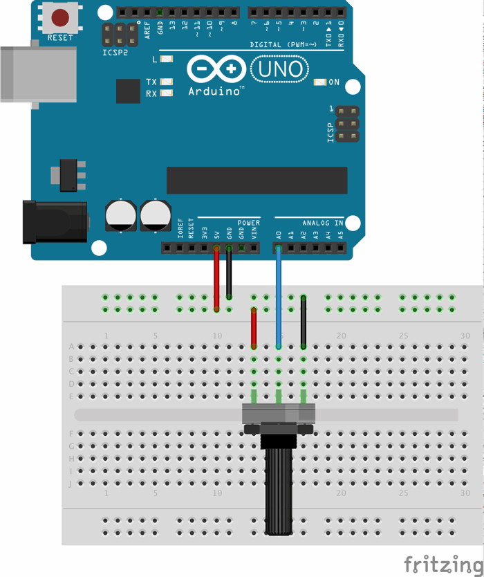
After wiring the circuit according to the diagram, the following code will print the value read from the potentiometer (on a scale of zero to one thousand twenty three) to the serial monitor.
const int POT =0;
int val =0;

void setup()
{
    Serial.begin(9600);
}

void loop()
{
    val = analogRead(POT);
    Serial.println(val);
    delay(500);
}
So now we know the basics of the Arduino. We learned how to write a program to interact with built in elements on the board. And how to wire the Arduino to an external component and get a reading from it. We still have a bit to go before we can read from the cars OBD-II port let alone send the data to Windows Azure. But fear not, we'll get there.
Connecting to the Internet
It's somewhat difficult to have an "Internet of Things" without the Internet (it's pretty much half of the name). There are shields (snap-on extensions to the base board that add functionality) for the Arduino that provide wifi support, but they start around fifty dollars. The Arduino Yun has built in Wifi and ethernet support but is also fifty dollars more expensive than the Uno. On the upside, both options give a more "holistic" interface to connecting to the internet via Wifi.
Having already spent a hundred dollars on my starter kit, it would be a tough sell to the Mrs. for another fifty to eighty dollars just to add wifi. Fortunately, I found the ESP8266 wifi module which comes in at a whopping 8 dollars definitely beneath the threshold of having to explain the purchase.
Getting up and running with the ESP is not the most simple endeavour. I spent a good three hours trying to get the most simple of scenarios (connecting to wifi and sending an HTTP request via the serial console) working. Out of the box, the ESP pretends to be a serial modem. You send it a series of AT commands to set the wireless mode (client, ap, or both). Then you can list nearby SSIDs and connect to one passing a WPA key if necessary. Finally you can open TCP channels and send requests over them and receive their response.
While the process seems tedious to work with programmatically, it was definitely something that could be done. So I began to roll up my sleeves to do the hard work at hand. Until I caught wind that the ESP had an SDK of its own. Turns out that the ESP is fully programmable just like the Arduino. Looking at the SDK I found that the ESP supported higher level API for Internet communications. It is built around FreeRTOS.
So my task became clear, I needed to download the ESP SDK and take my first adventure into "hardcore" embedded programming.
Programming the ESP
The ESP8266 is a relatively new chip on the market. And it's difficult to find reliable documentation on it. Until you find it. I've made a fork of a github project that automates the process of getting the toolchain and SDK allowing you to program the chip. The path of least resistance is to use a Unix like environment (Linux, MacOS, or Cygwin) to use the toolchain. I found a few issues leveraging it on Yosemite but found a solution that makes it work (read the last comment). Your Mileage May Vary on Linux and Windows.
Once you finally get the toolchain to build, you can take one of the samples and modify it for your needs. My needs are to support posting to azure eventhubs via a REST-based API.
Fortunately, I'm not the first person with those needs. The ESPDuino project is a firmware for the ESP and a library for the Arduino that allows you to simply make RESTful calls.
Leveraging the ESPDuino project it is trivial to make a call to a RESTful service. After connecting to the internet via wifi (using simpler commands than the AT set). You can make a call to your website like so:
rest.begin("yourapihere.cloudapp.net");
rest.post("someendpoint","mydata");
"mydata" can be a json string or a string of a number. Whatever your restful api accepts.
Publishing the website to windows azure can be done as either an azure website or via a VM depending on the needs of your application. Our next steps are to take the data from the car using the STN1100 chip and sending them to our application via REST.
Alternatives to the ESP8266
IoT is a rapidly moving field. Since I started this article, there has been a plugin released for Arduino that supports flashing the ESP directly. In addition there is the Oak development board which similar to the Arduino but built around the ESP8266. There is also the Particle (formerly Spark) Photon which is very well put together right out of the box including a cloud service and a mobile "tinker" app that lets you access pins directly from a mobile phone interface. Even better is Spark's upcoming Electron which uses a 2G or 3G mobile connection to cloud-enable your application (very handy when you're doing car telematics and don't want to use up your phone's wifi access point data).
Going forward, this article will be using the Photon for development until the Electron is available because they simplify the programming.
History
- 03/12/15: Initial version. Quickstart with Arduino
- 03/17/15: Added section on reading data from external components
- 03/19/15: Added introduction to the ESP8266
- 07/21/15: Updated with info about the Spark Photon
Michael Brown has worked in the software industry for almost 20 years including 12 years focused on .NET development. Michael is a five time recipient of the Microsoft MVP award in Client Application Development for his contributions to the WPF and Silverlight community. He has an article published in MSDN Magazine discussing WCF RIA Services. Michael has worked on a number of large scale applications for Fortune 500 hundred companies across a variety of industries including finance, healthcare, aerospace, government, retail, and energy.


 General
  News
News  Suggestion
  Question
  Bug
Bug  Answer
  Joke
Joke  Praise
  Rant
Rant  Admin
Admin 


