Introduction
In this tutorial, I will discuss how to create a system that notify any unauthorized activity or intrusion. I had used Arduino and PIR for activity detection and ESP8266 for WiFi connectivity. My Xperia Z1 is used for getting notification. I used populer notification app Pushbullet for getting notification and the Pushbullet APIs for sending notification from Arduino.
Prerequisite Knowledge
- Knowledge in Arduino and basic hardwares [ visit : www.arduino.cc]
- Idea about AT commands [ read : http://www.codeproject.com/Articles/85636/Introduction-to-AT-commands-and-its-uses ]
- PIR, how it works [ about : https://en.wikipedia.org/wiki/Passive_infrared_sensor ]
'Things' used
Arduino Mega 2560
ESP8266 serial WiFi ESP-01 variant
HC-SR501 PIR sensor
1000 µF capacitor, different resistors [ capacitor for WiFi power supply, resistor for voltage regulation ]
Single thread 0.5mm wires [ connector lead ]
Female-female jumper wires [ connectors ]
Xperia Z1 [ for Pushbullet app, any smartphone will do ]
My Laptop [ coding in arduino ]
Arduino IDE [v1.6.4]
What to DO
Environment set up : If you don't have arduino installed, install it from arduino website.
Setting up PIR :
I assume you need maximum sensitivity with minimum alert cycle to get better detection rate. Hence set PIR sensor pots like that :
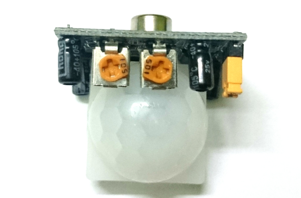

Now open the white sphere of the PIR sensor and you will see pin description : GND | OUT | VCC
Connect female jumpers with GND VCC and OUT.
Now connect other end of jumper pins (connected to PIR) to Arduino :
PIR GND -> Arduino GND
PIR VCC - > Arduino 5V
PIR OUT - > DIGITAL pin 2 [ you can choose pin according to your choice and change in arduino code also ]
To test your PIR you can use this code in Arduino Playground
So your PIR sensor is READY to work
Enabling Arduino to connect to internet via WiFi :
I used ESP8266 (variant ESP-01 ) serial WiFi module for my project which is pretty cheap. There are other variants available apart from ESP-01. There are different firmwares too available. I used the default one, AT firmware. Check this two images for connection reference
No connect ESP8266 with Arduino with jumper wire :
ESP8266 GND - > Arduino GND
ESP8266 UXTX (transmit pin) -> Arduino RX2 (arduino mega receiver pin, ie. Serial2 in code)
ESP8266 CH_PD (make HIGH) -> Arduino 5V (add one voltage regulator 0f 3.3 as ESP 8266 can tolerate 3.3v. I have used a resistor as I didn't have voltage regulator. But voltage regulator is preferred)
leave RST, GPIO2 and GPIO0 not connected
ESP8266 URXD (receiver pin) - > Arduino TX2 (arduino receiver pin ie. Serial2 in code)
ESP8266 VCC - > 3.3v of Arduino
ESP8266 has power issue at the time of data transmission. It draws power from arduino so much that arduino may restart if Arduino is powered via PC USB. Even with 5v power supply through power plug may not suffice. Hence it is always recommended to use external power supply for ESP8266. However in my experiment I used a quick & cheap solution for this. I used one 1000µF electrolyte capacitor to supply enough power to ESP8266.
longer pin - > ESP8266 VCC connected to 3.3v
shorter pin - > ESP8266 GND connected to arduino GND
So your ESP8266 WiFi module is READY to work
Pushbullet Notifier :
Pushbullet let you seemlessly notify your different devices through push notifications. We are going to use it's API for push notification of our PIR sensor. READ MORE about Pushbullet
Let's start.
Go to PushBullet
Register yourself, download chrome app and Smartphone app.
Log on to Pushbullet in your devices.
Now see how it works sending some push messages to your devices using app or chrome extension installed in your PC.
Go to API section
NOTE : Here all the API link and URLs are provided for https connection and Arduino can not use https as it is not that powerful to handle that. Hence we will use HTTP version of those APIs which is not mentioned here in pushbullet docs but I got this reference from github.
In pushbullet docs for pushing they had mentioned URL which is HTTPS, so we will use HTTP URL and port provided in that github project. Also we will add /pushbullet before and REST path they had mentioned.
Example :
for notification push to all devices , according to
pushbullet doc, REST path is :
/v2/pushesbut we will use : /pushbullet/v2/pushes
base URL : 173.17.168.19
port : 8181
Now check different API and read descriptions to know about them. You can use them later on for your enhanced version of this tutorial.
You need your authentication key to push from arduino. So go to your Account
Look for Access Token, copy & save this to your PC in secure place.
So Pushbullet is now READY to sending and receiving Push notification.
It's time to code now
Open this GitHub Project
Go to Experiments folder. There you will find MotionSense.ino, your code which will push notification to your Smart Devices.
Copy this code to arduino IDE and connect your arduino ( already set up with WiFi and PIR sensor ).
Now change these parameters :
#define SSID "YOURSSID" /* replace YOURSSID with your WiFi access point name */
#define PASS "YOURPASSWORD" /* replace YOUR PASSWORD with your WiFi access point password */
You may want to change PIR OUT pin to your desired pin
#define PIRPIN 2 /* change to your desired digital pin of your arduino */
#define AUTH_TOKEN "YOUR_TOKEN_FROM_YOUR_ACCOUNT";
Also use your access token as mentioned in above snippet.
Now compile and run.
It will take time for sensor calibration, WiFi module initialization and for connecting to your access point.
You can see these things in your Serial monitor.
After everything will done, it will start looping through main loop and you will see
"Everything fine | No intrusion "
in your serial monitor continuously.
Whenever you go go infront of your PIR sensor, it will detect movement and Push notification to your devices.
Understanding Code in brief
#defines are set of predefined parameters you need to change accordingly
In set up you can see initializing arduino Serial(). Serial2 is for WiFi serial access.
Understanding functions :
sensor_calibration ();
check_WiFi_radio ();
reset_wifi ();
set_wifi_mode ();
After setting WiFi mode you need to reset WiFi to set it
check_wifi_stat ();
connect_ssid ();
Upto this, your WiFi module initialized and connected, Now you need to check PIR reading whether it sensed motion or not. It will be under main loop.
pirRead ();
If something detected, then first you need to connect to Pushbullet server
server_connect ();
Now Push Notification
post ();
disconnect
server_disconnect ();
and loop through
SPECIAL NOTE
You can yse this post () function structure to stream any data to any RESTful API.
Related KnowledgeBase :
ESP8266 AT commands : https://room-15.github.io/blog/2015/03/26/esp8266-at-command-reference/
Pushbullet through Adafruit WiFi : https://github.com/klinker41/pushbullet-arduino/tree/master
ESP8266 Maker : http://espressif.com/en/products/esp8266/
Different ESP8266 modules : http://l0l.org.uk/2014/12/esp8266-modules-hardware-guide-gotta-catch-em-all/
ESP8266 Wiki : https://nurdspace.nl/ESP8266
PIR sensor : http://arduinobasics.blogspot.in/search/label/HC-SR501
about HC-SR501 : http://www.mpja.com/download/31227sc.pdf
Datasheet for PIR : http://www.datasheetspdf.com/datasheet/HC-SR501.html
more on PIR : https://arduinodiy.wordpress.com/2014/09/18/1093/
Passionate about Hardware and embedded system. Currently working in TCS Innovation Lab on IoT and M2M.


 General
  News
News  Suggestion
  Question
  Bug
Bug  Answer
  Joke
Joke  Praise
  Rant
Rant  Admin
Admin 


