Table of Contents
Introduction
This article is about BriefFiniteElement.NET, an open source library for analyzing solids and structures with FEM in C# hosted on Codeplex. Development of library and documentation (including this article on Codeproject) is ongoing.
You can check the library features from Features of BriefFiniteElement.NET.
Download
Every several days, the source code is changing (because of adding new features or fixing bugs), so I suggest you download the source code and simply build them to be sure that you have the latest binaries of BriefFiniteElement.NET.
Check the Downloading Latest Source Code for BriefFiniteElement.NET for instructions on simply downloading the latest source code of the project.
Examples
Before starting the examples, you have to add a reference to BriefFiniteElement.NET project or DLL file.
Example 1: A Simple Truss
In this example, I want to analyze a simple truss with 4 members as shown in the picture.
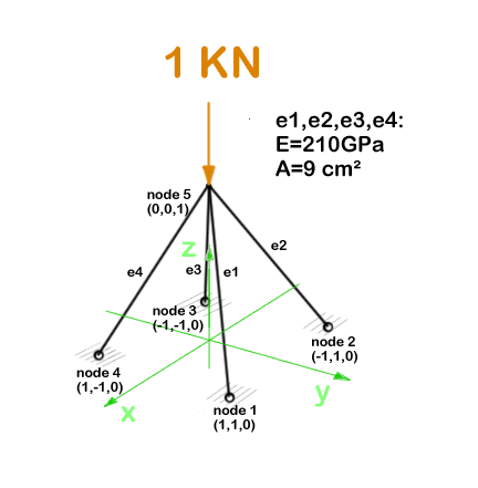
All members sections are the same, a square steel section with dimension of 3 cm. So the properties of members will be:
E = 210 GPa = 210*10^9 Pa = 210*10^9 N/M^2
A = 0.03m * 0.03m = 9 * 10^-4 m^2
We should do 5 steps before we solve the model:
- Create Model, Members and Nodes
- Add the Nodes and Elements to Model
- Assign geometrical and mechanical properties to Elements
- Assign Constraints to Nodes (fix the DoF s)
- Assign Load to Node
And finally, solve model with Model.Solve() method and then extract analysis results like support reactions or member internal forces or nodal deflections.
1. Creating Model, Members and Nodes
Creating Model
We should create a Finite Element model first and then add members and nodes to it:
var model = new Model();
Creating Nodes
We should create nodes like this. In BriefFiniteElement.NET, every node and element has a property of type string named Label and another one named Tag, both of which are inherited from BriefFiniteElementNet.StructurePart. In every Model, Label of every member should be unique among all members (both Nodes and Elements) unless the Label be equal to null which is by default. In the below code, we are creating 5 nodes of truss and assigning a unique Label to each one.
var n1 = new Node(1, 1, 0);
n1.Label = "n1";
var n2 = new Node(-1, 1, 0) {Label = "n2"};
var n3 = new Node(1, -1, 0) {Label = "n3"};
var n4 = new Node(-1, -1, 0) {Label = "n4"};
var n5 = new Node(0, 0, 1) {Label = "n5"};
Creating Elements
Then we have to create the elements. In BriefFiniteElement.NET, the TrussElement class represents a truss element in 3D.
var e1 = new TrussElement2Node(n1, n5) {Label = "e1"};
var e2 = new TrussElement2Node(n2, n5) {Label = "e2"};
var e3 = new TrussElement2Node(n3, n5) {Label = "e3"};
var e4 = new TrussElement2Node(n4, n5) {Label = "e4"};
2. Adding Nodes and Elements to Model
You can simply add the elements and nodes we created into the Model. Model has two members, Elements and Nodes which both represents an IList<T> of nodes and members, plus an AddRange method.
model.Nodes.Add(n1, n2, n3, n4, n5);
model.Elements.Add(e1, e2, e3, e4);
Please note that if Node or Element’s Label property is something other than null, then it should be unique among all nodes and elements.
3. Assigning Geometrical and Mechanical Properties to Elements
As elastic module for all members equals to 210 GPa and area of all members equals to 0.0009 m^2, we can set the element properties like this:
e1.A = e2.A = e3.A = e4.A = 9e-4;
e1.E = e2.E = e3.E = e4.E = 210e9;
4. Assigning Constraints to Nodes to Fix the DoFs
Now, we should make some DoFs of structure fix in order to make analysis logically possible.
In BriefFiniteElement.NET, every node has 6 degrees of freedom: X, Y, and Z rotations and X, Y, and Z translations. For every truss model, we have to fix rotational DoFs for each Node (X,Y and Z rotation). Also, the nodes 1 to 4 are also movement fixed, then nodes 1 to 4 should be totally fixed and node 5 should be rotation fixed. In BriefFiniteElement.NET, a struct named Constraint represents a constraint that is applicable to a 6 DoF node, it have Dx, Dy, Dz, Rx, Ry and Rz properties of type DofConstraint which is an enum and have two possible values 0 (Released) and 1 (Fixed). For making work easier, the Constraint struct has some predefined Constraints in its static properties for example Constraint.Fixed or Constraint.Free. Here is more detailed information:
| Property name | Description |
Fixed | All 6 DoFs are fixed |
Free | All 6 DoFs are released |
MovementFixed | 3 translation DoFs are fixed and 3 rotation DoFs are released |
RotationFixed | 3 translation DoFs are released and 3 rotation DoFs are fixed |
We can fix DoFs of nodes 1 to 4 like this:
n1.Constraints = n2.Constraints = n3.Constraints = n4.Constraints = new Constraint
(dx:DofConstraint.Fixed, dy:DofConstraint.Fixed, dz:DofConstraint.Fixed, rx:DofConstraint.Fixed,
ry:DofConstraint.Fixed, rz:DofConstraint.Fixed);
or:
n1.Constraints = n2.Constraints = n3.Constraints = n4.Constraints = Constraint.Fixed
and should fix the rotational DoFs of node 5:
n5.Constraints = Constraint.RotationFixed
5. Assigning Loads to Nodes
In BriefFiniteElement.NET, there is a struct named Force which represents a concentrated force in 3D space which contains 3 force components in X, Y and Z directions and three moment components in X, Y and Z directions. It has 6 double properties named Fx, Fy, Fz, Mx, My and Mz that are representing the load components. There are also two properties of type Vector for this struct named Forces and Moments. On setting or getting, they will use the Fx, Fy, Fz, Mx, My and Mz to perform operations:
public Vector Forces
{
get
{
return new Vector(fx,fy,fz);
}
set
{
this.fx = value.X;
this.fy = value.Y;
this.fz = value.Z;
}
}
Same is with Moments property. The Forces and Moments property do not actually store values in something other than 6 obvious properties.
As LoadCase and LoadCombination concepts are supported in BriefFiniteElement.NET, every Load should have a LoadCase. A LoadCase is simply a struct that has two properties: CaseName with string type and LoadType with LoadType type which is an enum and has some possible values:
public enum LoadType
{
      Default = 0,
      Dead,
      Live,
      Snow,
      Wind,
      Quake,
      Crane,
      Other
}
The LoadType.Default is a load type that is created for built in usage in library and it does not meant to have meaning like Dead, Live, etc. The LoadCase struct has a static property named LoadCase.DefaultLoadCase:
public static LoadCase DefaultLoadCase
{
get { return new LoadCase(); }
}
Which represents a LoadCase with LoadType of Default and CaseName of null. We will call such a LoadCase as DefaultLoadCase. For simplicity of usage in BriefFiniteElement.NET everywhere that you’ll prompt for a LoadCase, if you do not provide a LoadCase, then the LoadCase is assumed DefualtLoadCase by the library. For example, when you want to assign a load to a node, you should provide a LoadCase for it, like this:
var load = new NodalLoad(new Force(0, 0, -1000, 0, 0, 0), new LoadCase("Case1",LoadType.Dead));
but if you do not provide the LoadCase in the above code like this:
var load = new NodalLoad(new Force(0, 0, -1000, 0, 0, 0));
then the load case will be assumed DefaultLoadCase by the library.
Ok, next, we have to add 1KN load to node 5 like this, will do it with DefaultLoadCase:
var force = new Force(0, 0, -1000, 0, 0, 0);
n5.Loads.Add(new NodalLoad(force));
And finally, solve the model with model.Solve() method. Actually, solving the model is done in two stages:
- First stage is creating stiffness matrix and factorizing stiffness matrix which will take majority of time for analyzing.
- Second phase is analyzing structure against each load case which takes much less time against first stage (say for example 13 secs for the first stage and 0.5 sec for the second stage).
The first stage is done in model.Solve() method and the second stage will be done if it’ll be needed.
There are loads with different LoadCases that are applied to the Nodes and Elements. So the Node.GetSupportReaction() method have an overload which gets a LoadCombination and returns the support reactions based on the load combination. LoadCombination has a static property named LoadCombination.DefaultLoadCombination which has only one LoadCase in it (the DefaultLoadCase) with factor of 1.0. also everywhere that you should provide a LoadCombination, if you do not provide any, then DefaultLoadCombination will be considered by library. I’ve used DefaultLoadCase and DefaultLoadCombination in the library to make working with library easier for people who are not familiar with load case and load combination stuff.
For getting the support reaction for the truss, we can simply call Node.GetSupportReaction() to get support reaction for every node:
Force r1 = n1.GetSupportReaction();
Force r2 = n2.GetSupportReaction();
Force r3 = n3.GetSupportReaction();
Force r4 = n4.GetSupportReaction();
The plus operator is overloaded for Force struct, so we can check the sum of support reactions:
var rt = r1 + r2 + r3 + r4;
The forces (Fx, Fy and Fz) amount should be equal to sum of external loads and direction should be opposite to external loads to satisfy the structure static equilibrium equations.
All Codes Together
These are all the codes above for truss example.
Please note that these codes are available in BriefFiniteElementNet.CodeProjectExamples project in library solution.
private static void Example1()
{
Console.WriteLine("Example 1: Simple 3D truss with four members");
var model = new Model();
var n1 = new Node(1, 1, 0);
n1.Label = "n1";
var n2 = new Node(-1, 1, 0) {Label = "n2"};
var n3 = new Node(1, -1, 0) {Label = "n3"};
var n4 = new Node(-1, -1, 0) {Label = "n4"};
var n5 = new Node(0, 0, 1) {Label = "n5"};
var e1 = new TrussElement2Node(n1, n5) {Label = "e1"};
var e2 = new TrussElement2Node(n2, n5) {Label = "e2"};
var e3 = new TrussElement2Node(n3, n5) {Label = "e3"};
var e4 = new TrussElement2Node(n4, n5) {Label = "e4"};
e1.A = e2.A = e3.A = e4.A = 9e-4;
e1.E = e2.E = e3.E = e4.E = 210e9;
model.Nodes.Add(n1, n2, n3, n4, n5);
model.Elements.Add(e1, e2, e3, e4);
n1.Constraints = n2.Constraints = n3.Constraints =
n4.Constraints = Constraint.Fixed;
n5.Constraints = Constraint.RotationFixed;
var force = new Force(0, 1000, -1000, 0, 0, 0);
n5.Loads.Add(new NodalLoad(force));
model.Solve();
var r1 = n1.GetSupportReaction();
var r2 = n2.GetSupportReaction();
var r3 = n3.GetSupportReaction();
var r4 = n4.GetSupportReaction();
var rt = r1 + r2 + r3 + r4;
Console.WriteLine("Total reactions SUM :" + rt.ToString());
}
Example 2: Distributed Loads
In this example, I’m going to analyze a single sloped steel frame which its elements are under uniform distributed loads as shown in the image.

The purpose is to find the internal forces of members based on shown loads.
Creating Members and Nodes
First thing we are going to do is create the members and assign the geometrical and mechanical properties to them.
*Note: In the next code, two columns are ‘e1’ and ‘e4’ and two beams are ‘e2’ and ‘e3’.
var model = new Model();

var n1 = new Node(-10, 0, 0);
var n2 = new Node(-10, 0, 6);
var n3 = new Node(0, 0, 8);
var n4 = new Node(10, 0, 6);
var n5 = new Node(10, 0, 0);

model.Nodes.Add(n1, n2, n3, n4, n5);

var secAA = SectionGenerator.GetISetion(0.24, 0.67, 0.01, 0.006);
var secBB = SectionGenerator.GetISetion(0.24, 0.52, 0.01, 0.006);

var e1 = new FrameElement2Node(n1, n2);
var e2 = new FrameElement2Node(n2, n3);
var e3 = new FrameElement2Node(n3, n4);
var e4 = new FrameElement2Node(n4, n5);

e1.Geometry = e4.Geometry = secAA;
e2.Geometry = e3.Geometry = secBB;

e1.E = e2.E = e3.E = e4.E = 210e9;

e1.UseOverridedProperties = e2.UseOverridedProperties =
e3.UseOverridedProperties = e4.UseOverridedProperties = false;
In briefFiniteElement.NET, there are two ways to define section for a frame member. First is to define each of geometrical parameters (like area and second moments of area) by settings the FrameElement2Node.A or FrameElement2Node.Iy or FrameElement2Node.Iz, another way to do this is to define a polygon as section for frame element and library will automatically calculate the gemetrical parameters of section like area and second moments of area. By default, library assumes that you are defining geometrical parameters by settings FrameElement2Node.A, Iy or Iz. if you want to provide a polygon as section, you should set the FrameElement2Node.Geometry property (whose type is PolygonYz) and right after that, you should set the FrameElement2Node.UseOverridedProperties to false in order to tell the library to use Geometry instead of A, Iy, Iz, etc. There is also a useful static SectionGenerator class which provides some predefined sections like I sections or rectangular sections.
After creating elements and nodes, we can visualize the model in debug mode like the image below:
(For more information, see Add Debugger Visualizers for Visual Studio 2013, 2012 and 2010.)
*Note: Elements with UseOverridedProperties = true are shown with square sections (dimension of section automatically tunes for better visualization of elements) but elements with UseOverridedProperties = false will be shown with their real section with real dimension.
Next, we have to set boundary conditions or supports. As this problem is 2D (in x-z plane), we have to fix all movement in Y direction and also fix all rotations in x and z directions. As n1 and n5 are hinged supports, we also have to fix the movement of n1 and n5 in both x and z directions too.
n1.Constraints = n2.Constraints = n3.Constraints = n4.Constraints =
n5.Constraints = Constraint.FixedDy & Constraint.FixedRx &
Constraint.FixedRz;
n1.Constraints = n1.Constraints & Constraint.MovementFixed;
n5.Constraints = n5.Constraints & Constraint.MovementFixed;
Just have to note that the ‘&’ operator between two Constraint objects work like this: if both or one of Dx s are fixed, then result Dx is fixed, else Dx is released. It’s like Boolean operation while 'fixed' means '1' and 'free' means '0' !
Assigning Loads to Model
There are two distributed loads which are applying to model. Both are 1 Tonf/m which is equal to 10000 N/m but there is a difference as is illustrated before. The load which is applying to e2 element is in vertical direction but the load is applying to e3 element is perpendicular to e3 element. So it can be said the load on element e2 is a uniform load in GLOBAL z direction with amount of -10000 N/m and load which is applying to e3 is in element LOCAL z direction of coordination system and amount of -10000 N/m.
var ll = new UniformLoad1D(-10000, LoadDirection.Z, CoordinationSystem.Global);
var lr = new UniformLoad1D(-10000, LoadDirection.Z, CoordinationSystem.Local);

e2.Loads.Add(ll);
e3.Loads.Add(lr);
Checking for Errors in Model
In this example, if we do not set e1.Geometry property, we will get an error when equation system is solving because the structure is not stable. In this case, finding the error may seem to be simple but it's not always like this. For this reason, there is a Trace property for Model class which will let user see status of model while it's working. For example, on calling Model.Solve() for the first time, several separated tasks are being done. The first is calculating stiffness matrix of each element, next they should be assembled into global stiffness matrix KG, then kff should extract from KG and finally equation system that contains kff should be solved. Users do not see the information but information about this data is possible to achieve from Model.Trace. It's like System.Diagnostics.Trace functionality. The Trace members have TraceListeners property which is a list of ITraceListener objects. Once an ITraceListener object is added to this list, it will receive trace info of model. There is a ready ITraceListener class named WpfTraceListener in BriefFiniteElementNet.Controls project that can be used for seeing the information. Here is an example:
var wnd = WpfTraceListener.CreateModelTrace(model);
new ModelWarningChecker().CheckModel(model);
wnd.ShowDialog();
The first line creates a WpfTraceListener object and adds to Model.Trace.TraceListeners list. model.CheckForErrors() will check model for usual (obvious) errors and if any found, will be written into Model.Trace so we can see it in our window, and finally wnd.ShowDialog() will show the window. If, for example, we do not set Geometry property for e2 element, we will see this:
As you can see, there is a table and a record inside of it. First field is TimeStamp which is showing the time, next is a brief message about the record, next is Error ID (in case there is an error or warning) next is Level. Levels have three possible values:
For example of Level, look at the next pictures. Next is TargetField which is showing the target of record, in our case, it is e2 element and it has a link for more information (in this case, it redirects to error list page) and you can see description about error number MA10010 in the link.
If model does not contain error and we call wnd.ShowDialog() after call to model.Solve() like this:
var wnd = WpfTraceListener.CreateModelTrace(model);
new ModelWarningChecker().CheckModel(model);
wnd.ShowDialog();
model.Solve();
Will see something like this:
That contains information about nested tasks in solve process.
For more information, see Checking model for errors.
All together (Please note that these codes are available in BriefFiniteElementNet.CodeProjectExamples project in library solution):
private static void Example2()
{
Console.WriteLine("Example 1: Simple 3D Frame with distributed loads");
var model = new Model();
var n1 = new Node(-10, 0, 0);
var n2 = new Node(-10, 0, 6);
var n3 = new Node(0, 0, 8);
var n4 = new Node(10, 0, 6);
var n5 = new Node(10, 0, 0);
model.Nodes.Add(n1, n2, n3, n4, n5);
var secAA = SectionGenerator.GetISetion(0.24, 0.67, 0.01, 0.006);
var secBB = SectionGenerator.GetISetion(0.24, 0.52, 0.01, 0.006);
var e1 = new FrameElement2Node(n1, n2);
e1.Label = "e1";
var e2 = new FrameElement2Node(n2, n3);
e2.Label = "e2";
var e3 = new FrameElement2Node(n3, n4);
e3.Label = "e3";
var e4 = new FrameElement2Node(n4, n5);
e4.Label = "e4";
e1.Geometry = e4.Geometry = secAA;
e2.Geometry = e3.Geometry = secBB;
e1.E = e2.E = e3.E = e4.E = 210e9;
e1.G = e2.G = e3.G = e4.G = 210e9/(2*(1 + 0.3));
e1.UseOverridedProperties =
e2.UseOverridedProperties = e3.UseOverridedProperties =
e4.UseOverridedProperties = false;
model.Elements.Add(e1, e2, e3, e4);
n1.Constraints =
n2.Constraints =
n3.Constraints =
n4.Constraints =
n5.Constraints =
Constraint.FixedDY & Constraint.FixedRX &
Constraint.FixedRZ;
n1.Constraints = n1.Constraints & Constraint.MovementFixed;
n5.Constraints = n5.Constraints & Constraint.MovementFixed;
var ll = new UniformLoad1D(-10000, LoadDirection.Z, CoordinationSystem.Global);
var lr = new UniformLoad1D(-10000, LoadDirection.Z, CoordinationSystem.Local);
e2.Loads.Add(ll);
e3.Loads.Add(lr);
var wnd = WpfTraceListener.CreateModelTrace(model);
new ModelWarningChecker().CheckModel(model);
wnd.ShowDialog();
model.Solve();
}
Analyzing the Model and Getting Internal Forces
For analyzing the model, we should simply call the Model.Solve() method. After model is solved, we can get the internal force of members in any position of member's length with calling GetInternalForce method of FrameElement2Node class.
Following is the moment diagram based on output of FrameElement2Node.GetInternalForce() for this model.
Example 3: Inclined Frame
(Link to full article.)
Consider the inclined frame shown in the figure below:
There are two loads on top elements. One has a 6 kn/m magnitude and its direction is vertical, another one has 5kn/m magnitude and it is perpendicular to the <cite>e2</cite> element.
Codes
Step 1: Create model, nodes and elements:
var model = new Model();

model.Nodes.Add(new Node(-10, 0, 0) { Label = "n0" });
model.Nodes.Add(new Node(-10, 0, 6) { Label = "n1" });
model.Nodes.Add(new Node(0, 0, 8) { Label = "n2" });
model.Nodes.Add(new Node(10, 0, 6) { Label = "n3" });
model.Nodes.Add(new Node(10, 0, 0) { Label = "n4" });

model.Elements.Add(new BarElement(model.Nodes["n0"], model.Nodes["n1"]) { Label = "e0"});
model.Elements.Add(new BarElement(model.Nodes["n1"], model.Nodes["n2"]) { Label = "e1"});
model.Elements.Add(new BarElement(model.Nodes["n2"], model.Nodes["n3"]) { Label = "e2" });
model.Elements.Add(new BarElement(model.Nodes["n3"], model.Nodes["n4"]) { Label = "e3" });
Step 2: Define support nodes (nodal constraints):
model.Nodes["n0"].Constraints = model.Nodes["n4"].Constraints = Constraints.Fixed;
Step 3: Assign material and section to the elements:
var secAA = new Sections.UniformGeometric1DSection
            (SectionGenerator.GetISetion(0.24, 0.67, 0.01, 0.006));
var secBB = new Sections.UniformGeometric1DSection
            (SectionGenerator.GetISetion(0.24, 0.52, 0.01, 0.006));
var mat = Materials.UniformIsotropicMaterial.CreateFromYoungPoisson(210e9, 0.3);

(model.Elements["e0"] as BarElement).Material = mat;
(model.Elements["e1"] as BarElement).Material = mat;
(model.Elements["e2"] as BarElement).Material = mat;
(model.Elements["e3"] as BarElement).Material = mat;

(model.Elements["e0"] as BarElement).Section = secAA;
(model.Elements["e1"] as BarElement).Section = secBB;
(model.Elements["e2"] as BarElement).Section = secBB;
(model.Elements["e3"] as BarElement).Section = secAA;
Step 4: Assign loads to elements:
var u1 = new Loads.UniformLoad(LoadCase.DefaultLoadCase,
                   new Vector(0,0,1), -6000, CoordinationSystem.Global);
var u2 = new Loads.UniformLoad(LoadCase.DefaultLoadCase,
                   new Vector(0,0,1), -5000, CoordinationSystem.Local);

model.Elements["e1"].Loads.Add(u1);
model.Elements["e2"].Loads.Add(u2);
Step 5: Analyze the model:
model.Solve_MPC();
Step 6: Get analysis results:
Usually, the aim of analysis is to find some quantities like internal force and nodal displacements. After solving the model, we can find nodal displacements with <cite>Node.GetNodalDisplacement</cite>, and BarElement’s internal force with BarELement.GetInternalForceAt and BarElement.GetExactInternalForceAt methods. There is a difference between the two methods. Details are available in Internal Force And Displacement section in documentation of <cite>BarElement</cite>.
For example, the support reaction of node <cite>N3</cite> can be found and printed to application Console like this:
var n3Force = model.Nodes["N3"].GetSupportReaction();
Console.WriteLine("Support reaction of n4: {0}", n3Force);
This is the result of print on console:
Support reaction of n4: F: -37514.9891729259, 0, 51261.532772234, M: 0, -97714.6039503916, 0
Element’s internal force can be found like this: For example, you need to find internal force of element in a point with distance of 1m (one meter) of start node. We can use <cite>BarElement.GetInternalForceAt()</cite> method to simply get the internal force of element at desired location of length of element, but there is an important thing here: and that is the input of <cite>BarElement.GetInternalForceAt()</cite> method is not in meter dimension nor any other standard units of measuring length. The input is in another coordination system named iso-parametric crs. The isoparametric crs is widely used in FEM. More details about BarElement does have a method for converting.
The whole source code exists in the BarIncliendFrameExample.cs file.
Example 4: Load Combination
(Link to full article)
There are two concepts named LoadCase and LoadCombination in this library and many other software. A `LoadCase` defines the group of loads. For example, in the structure below, there is a “dead” load and a “live” load, and two “earthquake” loads, in X and Y direction on n4 node:
Model with 4 type of load
The LoadCase struct has a nature property (an enum type) and a title property (with string type). LoadNature can be: Default, Dead, Live, Snow, Wind, Quake, Crane and Other.
- So there can be 4 LoadCases for this example:
-
- Case 1: Nature = Dead, Title = “D1”
- Case 2: Nature = Live, Title = “L1”
- Case 3: Nature = Quake, Title = “Qx”
- Case 4: Nature = Quake, Title = “Qy”
We will do these steps before solving model:
- Step 1: Create Model, prepair and add Elements and Nodes.
- Step 2: Assign Constraints to Nodes (fix the DoF s).
- Step 3: Assign Load to Node.
Step 1: Create Model, Prepair and Add Elements and Nodes
To make the model, elements and loads:
var model = new Model();
model.Nodes.Add(new Node(0, 0, 0) { Label = "n0" });
model.Nodes.Add(new Node(0, 2, 0) { Label = "n1" });
model.Nodes.Add(new Node(4, 2, 0) { Label = "n2" });
model.Nodes.Add(new Node(4, 0, 0) { Label = "n3" });
model.Nodes.Add(new Node(0, 0, 1) { Label = "n4" });
model.Nodes.Add(new Node(0, 2, 1) { Label = "n5" });
model.Nodes.Add(new Node(4, 2, 1) { Label = "n6" });
model.Nodes.Add(new Node(4, 0, 1) { Label = "n7" });
var a = 0.1 * 0.1;
var iy = 0.1 * 0.1 * 0.1 * 0.1 / 12.0;
var iz = 0.1 * 0.1 * 0.1 * 0.1 / 12.0;
var j = 0.1 * 0.1 * 0.1 * 0.1 / 12.0;
var e = 20e9;
var nu = 0.2;
var sec = new Sections.UniformParametric1DSection(a, iy, iz, j);
var mat = Materials.UniformIsotropicMaterial.CreateFromYoungPoisson(e, nu);
model.Elements.Add(new BarElement(model.Nodes["n0"],
model.Nodes["n4"]) { Label = "e0", Section = sec, Material = mat});
model.Elements.Add(new BarElement(model.Nodes["n1"],
model.Nodes["n5"]) { Label = "e1", Section = sec, Material = mat });
model.Elements.Add(new BarElement(model.Nodes["n2"],
model.Nodes["n6"]) { Label = "e2", Section = sec, Material = mat });
model.Elements.Add(new BarElement(model.Nodes["n3"],
model.Nodes["n7"]) { Label = "e3", Section = sec, Material = mat });
model.Elements.Add(new BarElement(model.Nodes["n4"],
model.Nodes["n5"]) { Label = "e4", Section = sec, Material = mat });
model.Elements.Add(new BarElement(model.Nodes["n5"],
model.Nodes["n6"]) { Label = "e5", Section = sec, Material = mat });
model.Elements.Add(new BarElement(model.Nodes["n6"],
model.Nodes["n7"]) { Label = "e6", Section = sec, Material = mat });
model.Elements.Add(new BarElement(model.Nodes["n7"],
model.Nodes["n4"]) { Label = "e7", Section = sec, Material = mat });
Step 2: Assign Constraints to Nodes (fix the DoF s)
model.Nodes["n0"].Constraints =
  model.Nodes["n1"].Constraints =
    model.Nodes["n2"].Constraints =
      model.Nodes["n3"].Constraints =
        Constraints.Fixed;
Step 3: Assign Load to Nodes
This is the main purpose of this example, the LoadCase and LoadCombination types. In framework, every Load does have a property named LoadCase. This LoadCase property will help us to distribute all Loads into groups. We want to do this because we should solve the model for each LoadCase separately. In this example, we will create 4 load cases:
- a load case with name
d1 and load type of dead for dead loads on top horizontal elements - a load case with name
l1 and load type of live for live loads on top horizontal elements - a load case with name
qx and load type of quake for 5kN concentrated force applied to n4 node - a load case with name
qy and load type of quake for 10kN concentrated force applied to n4 node
var d_case = new LoadCase("d1", LoadType.Dead);
var l_case = new LoadCase("l1", LoadType.Dead);
var qx_case = new LoadCase("qx", LoadType.Quake);
var qy_case = new LoadCase("qy", LoadType.Quake);
Then, we should create two distributed loads for top beams:
var d1 = new Loads.UniformLoad(d_case, -1 * Vector.K, 2e3, CoordinationSystem.Global);
var l1 = new Loads.UniformLoad(l_case, -1 * Vector.K, 1e3, CoordinationSystem.Global);

var qx_f = new Force(5000 * Vector.I, Vector.Zero);
var qy_f = new Force(10000 * Vector.J, Vector.Zero);
Note that we’ve set the load case of these two loads by passing d_case and l_case into constructor of Loads.UniformLoad class.
Next, we will add d1 and l1 and two other nodal loads to all top elements. you should note that adding same load to more that one element is possible and will work like creating identical loads for each element.
model.Elements["e4"].Loads.Add(d1);
model.Elements["e5"].Loads.Add(d1);
model.Elements["e6"].Loads.Add(d1);
model.Elements["e7"].Loads.Add(d1);
model.Elements["e4"].Loads.Add(l1);
model.Elements["e5"].Loads.Add(l1);
model.Elements["e6"].Loads.Add(l1);
model.Elements["e7"].Loads.Add(l1);
model.Nodes["n4"].Loads.Add(new NodalLoad(qx_f, qx_case));
model.Nodes["n4"].Loads.Add(new NodalLoad(qy_f, qy_case));
model.Solve_MPC();
As mentioned before, all loads in BFE should inherit from NodalLoad or ElementLoad. Both of these loads have a property named LoadCase property of type `LoadCase`. So every load in BFE will have the LoadCase property. On the other hand, to get analysis result of model - like internal force on elements, or nodal displacements or support reactions - a parameter of type LoadCombination should pass to the appropriated method. For example, to get internal force of bar element, this method should be called:
BarElement.GetInternalForceAt(double x, LoadCombination combination);
Or to get support reaction of a node, this method should be used:
Node.GetSupportReaction(LoadCombination combination);
A `LoadCombination` in a list of LoadCases with a multiplier for each one. Internally, it does use `Dictionary<LoadCase,double>` to keep the list. For example, if want to find support reaction for node n3 with loadCombination D + 0.8 L:
var combination1 = new LoadCombination();
combination1[d_case] = 1.0;
combination1[l_case] = 0.8;
var n3Force = model.Nodes["N3"].GetSupportReaction(combination1);
Console.WriteLine(n3Force);
or for finding internal force of e4 element with combination D + 0.8 L at its centre:
var e4Force = (model.Elements["e4"] as BarElement).GetInternalForceAt(0, combination1);
Console.WriteLine(e4Force);or ds
Performance of BriefFiniteElement.NET
Look at Performance of BriefFiniteElement.NET
Points of Interest
At this time, the project has some features that are listed on Features of BriefFiniteElement.NET. There are also a set of features I planned to include in this library which I am working.
Support
If you have questions about the library or you've found a bug or have any idea/feature request, please let me know via DISCUSSION or ISSUEs on Github.
Contribute
If you have good knowledge in linear fem, look HERE and help us solve our problems.
TODO
These examples will be added to this article:
- Example 1: Simple Truss (Done)
- Example 2: Element Distributed Load (Done)
- Example 3: Load Combination (Done)
- Example 4: Analyzing grid and checking result for statically equilibrium
History
- 9th July, 2014 - First version
- 26th July, 2014 - Added Example #2 (Element Distributed Load)
- 5th January, 2020 - Added Example #3 (Load Combination)
I've done M.Sc. in civil engineering and have several years of experiences in C# and WPF.


 General
  News
News  Suggestion
  Question
  Bug
Bug  Answer
  Joke
Joke  Praise
  Rant
Rant  Admin
Admin 


