Introduction
If, for whatever reason, you need to code custom hit testing, there’s an extremely high speed method you can employ that will eliminate all comparisons and bounds testing, immediately returning an index to the area that a passed set of coordinates falls inside. I call it “mapped hit testing.” I developed this method over the course of many years of coding. While I came up with it on my own, it’s more likely than not that it’s been used before; for all I know, Windows, Linux, and/or other operating systems may have employed it from day one. I only know I’ve never seen the method mentioned anywhere. The approach is OS independent; it can be implemented on any operating system.
The Method
The method is inordinately simple, at least conceptually: two arrays of memory are reserved; the first, the horizontal flags list, is the monitor’s display area width, and the second is its display area height. The horizontal array holds one value per column of pixels on the monitor. For a 1920 pixel wide monitor, a maximum of1920 values are reserved. The vertical array is the same, representing each row of pixels on the monitor. For a monitor height of 1080 pixels, the maximum size of the vertical array is 1080 array elements wide. These numbers will drop depending on the overall area to be covered. The example used in this article has a 640 x 480 dialog box serving as a host window for four virtual areas. Since the dialog is modal, only mouse movement within its bounds is tracked, so the horizontal array is 640 elements, while the vertical is 480 elements.
The number of bits in each value of the arrays is the number of areas that can be mapped. If you use 32 bits per entry, you can map up to 32 areas. If you use 64 bits, you can map up to 64 areas. If you need to go even larger, you can use SSE instructions to reference larger values in the arrays. It’s entirely possible to use one size for the horizontal array and another for the vertical array – you just need to work with the value sizes you set accurately.
My own implementation of this method is a custom dialog box. 4 of its 44 controls are virtual – Windows does not see them as controls at all, thus there is no inherent mouse handling for them. The dialog handler itself must detect mouse movement over these areas and virtualize handling accordingly. This is where the mapping approach is implemented.
With only 4 controls being listed, I need no more than 4 bits to represent them uniquely. With 8-bit bytes being the smallest feasible size for each array entry, that’s what is used for this case. If I wanted to cover the entire desktop, then monitor size would be determined at run time; as such, the arrays would be allocated then. On my own 3840 x 2160 monitor, the arrays for the full desktop would 3840 bytes for the horizontal, and 2160 bytes for the vertical. However in this example, I'm only mapping the space within my 640 x 480 dialog box.
With byte-sized array entries, I can flag the locations of up to 8 virtual areas: 8 bits per byte.
We’ll use an arbitrary example of the following area x, y, width, and height for my four areas:
Area 0: x = 35, y = 027, width = 086, height =  34; flag with bit 0 or a value of 1
Area 1: x = 85, y =  63, width = 113, height = 258; flag with bit 1 or a value of 2
Area 2: x = 17, y = 113, width = 393, height = 198; flag with bit 2 or a value of 4
Area 3: x =  6, y = 145, width = 411, height = 271; flag with bit 3 or a value of 8
The coordinates shown above are relative to the dialog window’s upper left corner. These are not screen coordinates; they are not client coordinates. They are dialog window relative.
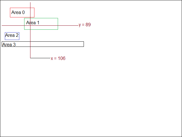
The image below shows the actual virtual areas used in this article, mapped out on a 640 x 480 window which, if properly drawn, would be the host dialog box.
Writing the Map
For area 0, the x coordinate is 17, so the 17th entry in the horizontal array is located. Starting with and including that location, since the area’s width is 227 pixels, 227 consecutive array entries are flagged with a value of 1 (bit 0 set) to represent area 0. Using the same process, locate the 196th entry in the vertical array, since the area’s y coordinate is 196. The height of the area is 109 pixels, so 109 entries in the vertical array, starting with entry 196, are flagged with a value of 1.
This process is repeated for the other three areas, moving to a value of 2, 4, and 8 respectively. Each control shifts its flag bit left one bit. Logical OR is used to apply each flag value; both arrays are zeroed before starting the mapping process. Values will often overlap; array entries can and often will represent more than one virtual area. This is why logical OR is used to flag area locations – so as not to upset any areas already flagged.
That’s all there is to the mapping process.
Reading the Map
To read the map, fasten your seat belt. There are no compares, tests, ifs, ands, or buts.
A mouse movement message comes into my dialog box’s callback function. During the dialog's initialization, I load its screen-relative coordinates into a static memory rect (rectangle; left, top, right, bottom) structure so I don’t need to continually retrieve it when the dialog box is not moving. Remember: this rectangle is screen relative, because when I extract the mouse coordinates when the message is received, those coordinates are also screen relative.
Since the mapping process is relative to the dialog box, the map will not have to be rebuilt if the dialog box moves. If it was resized, then rebuilding the map would be required.
The dialog box window’s screen-relative x coordinate is subtracted from the screen-relative mouse x coordinate. This makes the mouse x coordinate I’m working with dialog window relative – which is the way my virtual areas were mapped.
Repeat the process for the mouse y coordinate, subtracting the dialog window’s screen-relative y coordinate from the screen-relative mouse y coordinate. I now have mouse x and mouse y relative to the upper left corner of the dialog box, matching the coordinate system used to create the mouse maps.
Suppose a message is received where, after conversion, the mouse x coordinate is 106. As it turns out, the 106th horizontal array element (see the image above) will be set to 0x03 or 00000011b, because areas 0 and 1 span that column of pixels.
The mouse y coordinate sent to my dialog handler is 89. Area 1, flagged by 0x02 or 00000010b, is retrieved by reading the 89th element of the vertical array.
The horizontal value is 0x03. The vertical value is 0x02. Logical AND the two together. Any flag values not present both horizontally and vertically will be zeroed. In this example, the result of the logical AND will be 0x03 AND 0x02 = 0x02. This is bit 1, or area 1. The index of the area is the bit remaining set after the logical AND.
You could have overlapping areas; i.e., a virtual scroll bar appearing inside a client area. I apply flags in Z order to handle these kinds of cases. The bottom of the Z order – in the case of this example, the client area – is a lower bit index than the scroll bar, which is higher in the Z order. As an arbitrary example, the client area might be bit index 2 while the scroll bar is bit index 3. After the logical AND of the horizontal and vertical array values, both bits 2 and 3 will be set. Since I built my mapping process to match the Z order of my areas, I will always want the highest set bit after the logical AND. In this case, it’s bit 3. (Intel architecture provides the BSR or bit scan reverse instruction to identify the highest set bit – using intrinsics will render the architecture irrelevant.) So area 3 – since bit 3 was the highest bit set after the logical AND – would represent the scroll bar, and it would be known that the mouse cursor is over area 3.
That’s the process, in a nutshell.
Odds and Ends
For 16-bit entries, shift the x and/or y coordinate left by 1 bit, which is the equivalent of multiplying by 2 bytes per pixel row and/or column. For 32-bit entries, shift left by 2 bits, the same as multiplying by 4 bytes per pixel row and/or column. And so forth.
The process provides 100% accuracy and near-instant determination of the virtual area a given x, y coordinate pair is over with no searching, compares, or if statements. There is no bounds checking inside rectangle after rectangle, dragging down performance. In my own assembly code, on Intel architecture, the process involves four ASM instructions: load the X array value, load the Y array value, AND, then BSR.
It’s a very elegant system that will definitely require a little patience and a lot of fine-tuning during development to get everything lined up and working properly. But once it’s in place, the process of hit testing becomes so fast that its burden on the CPU is negligible. I have used this process in multiple applications; it works so well that it’s soon forgotten as I move on to other tasks.
On today’s systems, the 6,000 bytes I use for my map arrays is not even worth mentioning. Some portion of that would be used anyway by the code required to lumber along and bound-check rectangle after rectangle. If you wanted to map up to 64 unique areas, this value would go 8 times higher, to 48,000 bytes of memory. In my view, this is still in the arena of “who cares?” considering the performance boost provided (keeping in mind that my own ASM apps are really, really tiny).
Keep in mind that if you’re going to map a full window with this process, keep the window borders (for dragging) at the lowest flag values; the caption above that, the caption buttons and system menu icon above that, and finally the rest of the elements. The client area as a whole uses a flag value lower than the areas appearing inside the client area.
I have never had a problem mapping an entire window this way. As long as Z order is kept in mind when assigning flag values, the system works inordinately well, and really it falls back on the old tradeoff: higher performance carrying the cost of a little more memory usage and a little more development time.
I work as a contract developer, specializing in assembly language driver software for specialized hardware. I also focus on identifying and removing performance bottlenecks in any software, using assembly language modifications, as well as locating hard-to-find bugs. I’m a specialist; I prefer to stay away from everyday, mundane development. I can fix problems in high level languages but as a rule I don’t like working with them for general development. There is no shortage of experienced developers in any language besides assembly. I am very much a niche programmer, a troubleshooter; the closer to the hardware I work, the happier I am. I typically take on the tasks others can’t or don’t want to do.


 General
  News
News  Suggestion
  Question
  Bug
Bug  Answer
  Joke
Joke  Praise
  Rant
Rant  Admin
Admin 


