Table of Contents
3D Basics
This section will explain the basics to understanding the concepts involved in creating a 3D scene in XAML.
Coordinate system
Additional links: MSDN.
By this point, you should be familiar with using 2D coordinates to place XAML object. Placing an object is very similar but requires an extra value, and rather than using whole numbers, all values can be floating point numbers (uses decimal places).
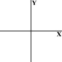
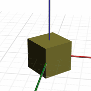
Below is a representation of a 2D Cartesian coordinate system, which can be used to define any point in 2D. Next to that is a 3D coordinate system, the line at an angle labeled Z generally represents depth, or distance from your point of view.
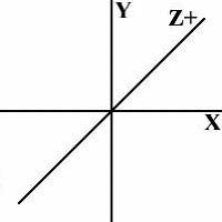
That’s the standard way to visualize things in the two coordinate systems. It's generally accepted in 2D computer graphics that 0,0 represents the top left of the screen. While that could be the case, in 3D it rarely is, where 0,0,0 is displayed in the screen depends on completely where the camera is (your point of view). Luckily, in XAML, there is an easy way to position an entire scene as you would any other 2D control, the ViewPort3D.
Setting up a scene
The very first thing you need to setup a 3D scene is to define the ViewPort3D, this will position your scene on the canvas.
<ViewPort3D Canvas.Top="50" Canvas.Left="50" Width="300" Height="300">
    #Scene definition
</Viewport>
The next thing you absolutely must have is a camera. Without a camera to represent your point of view (POV), you won't be seeing much. This would fit into the above code in the scene definition section.
<ViewPort3D.Camera>
    <PerspectiveCamera
        Position="-250,250,200"
        LookAtPoint="0,0,0"
        Up="0,1,0"
        FieldOfView="40"
        NearPlaneDistance="1"
        FarPlaneDistance="500"
    />
</ViewPort3D.Camera>
This needs a little bit of explanation, but it's easiest to think of in terms of an eye. The first three sets of numbers position and orient the eye, Position gives the world position of where the eye will be, next is the LookAtPoint which describes the point in space the eye is looking at. The first two alone describe a lot but there is not enough to describe the full orientation, it might help to think of Up as a direction for a head tilt. The FieldOfView is the angle in degrees describing your range of view, think of it as projecting a cone out from the eye, anything in that cone can be seen.
The NearPlaneDistance and FarPlaneDistance together describe your depth range of view. If you measure the distance from the eye to any object, and that distance outside the near and far plane, you will not see that object. The near and far planes are fairly significant because they affect more than just if you can see an object, they affect how accurate the Depth Buffer in DirectX will be. So, avoid the urge to just set the far plane to 1 zillion so you see everything. The Depth Buffer has limited precision, so if there is too much space to cover, you will notice rendering anomalies.

A camera is no good if you don’t have any objects to look at. You need some models, but to have models, you first need a model collection. Model collections contain the models as well as lights.
<ViewPort3D>
    #Scene definition
    <ViewPort3D.Models>
        <Model3DCollection>
            #models and Lights go in here
        </Model3DCollection>
    </ViewPort3D.Models>
</ViewPort3D>
Defining lights
A well lit scene always looks better. Without any lights, there is a default ambient light color but you really want to add some lights to create atmosphere. There are 4 basic types of lights.
- Ambient
An omnipresent light (requires no position) that will affect all objects and all sides of the objects equally.
AmbientLight Color="#404040"/>
- Directional
Another omnipresent light, this will affect all objects in a scene but will light the object based on its direction. Any part of an object facing towards the direction of the light will be fully lit, facing away will be unlit.
<DirectionalLight Color="#C0C0C0" Direction="-0.5,-0.25,-1"/>
- Point
Emits light from a single point equally in all directions. It requires a position and color and falloff values.
*not implemented.
- Spot
Emits light at a target; requires a position, orientation direction, a color, a inner and outer cone size, and some falloff values.
*not implemented.
Creating objects
There are a few ways you can get an object into a scene.
- Import an X-file
Probably the easiest way assuming you have a .x file available. The downside to doing this is that the file must exist and be accessible to the viewer.
<MeshPrimitive3D>
    <MeshPrimitive3D.Mesh>
        <Mesh3D XFile3DSource="TorusKnot.x"/>
    </MeshPrimitive3D.Mesh>
</MeshPrimitive3D>
- Define the mesh in XAML
This is a little more complicated, you have to define the mesh points, indices for triangles, and point normals. Unlike the X-file source, this doesn’t require any outside files.
<MeshPrimitive3D>
    <MeshPrimitive3D.Mesh>
        <Mesh3D
Normals="0,-1,0 0,1,0 0,0,-1 1,0,0 0,0,1 -1,0,0 0,-1,0 0,1,0 ...
Positions="-5,0,-5 5,0,-5 -5,0,5 5,0,5 -5,10,-5 5,10,-5 ...
TriangleIndices="0,3,2 3,0,1 4,7,5 7,4,6 8,9,10 9,8,11 ...
/>
    </MeshPrimitive3D.Mesh>
</MeshPrimitive3D>
* Fortunately there is a tool on the Internet that can convert an X-file to a XAML definition: MSDN.
- Define a reference mesh
Similar to a XAML defined mesh, this is defined globally so it can be reused. Reusable definitions are defined in Canvas.Resources and can be used and reused in any Mesh3D. Note the xmlns:def="Definition" defined in the Canvas tag.
<Canvas xmlns="http://schemas.microsoft.com/2003/xaml" xmlns:def="Definition">
    <Canvas.Resources>
        <Mesh3D def:Name="Box"
Normals="0,-1,0 0,1,0 0,0,-1 1,0,0 0,0,1 -1,0,0 0,-1,0 0,1,0 0,0,-1 ...
Positions="-5,0,-5 5,0,-5 -5,0,5 5,0,5 -5,10,-5 5,10,-5 -5,10,5 5,10,5 ...
TriangleIndices="0,3,2 3,0,1 4,7,5 7,4,6 8,9,10 9,8,11 1,7,12 7,1,13...
        />
</Canvas.Resources>…
Used later in a model collection:
<MeshPrimitive3D Mesh="{Box}"/>
Defining materials
If you have opted to define your mesh object in XAML or you linked to an X-file with no material information, your model will most likely end up black. Defining a solid color brush is fairly simple, it just needs a color.
<MeshPrimitive3D.Material>
    <BrushMaterial Brush="green"/>
</MeshPrimitive3D.Material>
And here’s a more complete sample animating the solid brush color:
<MeshPrimitive3D Mesh="{Box}">
    <MeshPrimitive3D.Material>
        <BrushMaterial>
            <BrushMaterial.Brush>
                <SolidColorBrush>
                    <SolidColorBrush.ColorAnimations>
                        <ColorAnimation
                            From="Green"
                            To="Red"
                            Begin="0.5"
                            Duration="1"
                            AutoReverse="True">
                    </SolidColorBrush.ColorAnimations>
                </SolidColorBrush>
            </BrushMaterial.Brush>
        </BrushMaterial>
    </MeshPrimitive3D.Material>
Aside from solid colors, you might want to texture your object with a texture. You can specify an image file, the size, and the opacity.
<BrushMaterial.Brush>
    <ImageBrush
        ImageSource="TextureName.jpg"
        ViewPort="0 0 1024 1024"
        Opacity="1.0"
    />
</BrushMaterial.Brush>
Hit testing
Hit testing on 3D objects is fairly easy to implement, at the moment only click is supported.
…
<MeshPrimitive3D Click="OnClick">
<MeshPrimitive3D.Material>
…
Camera controllers
Camera controllers are handy if you want to be able to navigate a 3D scene manually. The downside here is, this is not an Avalon support tag and will not work in Longhorn.
There are two types of camera controllers:
- Free
This movement mode is unlimited and allows the user to move anywhere and in any direction.
- Left click drag to change heading.
- W,S to move forward and back.
- A,D to move left and right.
- Q,E to move up and down.
<PerspectiveCamera
    Position="-250,0,0"
    LookAtPoint="0,0,0"
    Up="0,1,0" NearPlaneDistance="1"
    FarPlaneDistance="500"
    FieldOfView="40"
    CameraController="Free"/>
</ViewPort3D.Camera>
- Targeted
A target camera allows the user to orbit around a particular point as well as move in and out. The keys are the same as the free camera mode but movement is limited to around the target.
<PerspectiveCamera
    Position="-250,0,0"
    LookAtPoint="0,0,0"
    Up="0,1,0" NearPlaneDistance="1"
    FarPlaneDistance="500"
    FieldOfView="40"
    CameraController="Target"/>
</ViewPort3D.Camera>
Transforms
Additional links: MSDN.
At this point, you should be able to make a scene with a camera, add some objects, and light them all up. If you’ve tried it, you may have noticed all your objects start at 0,0,0 and stay there. Transforms are going to allow to define how you want objects in the scene placed, oriented, sized, as well as animated.
Much like the models, transforms require a collection. All transforms must be listed within the collection, the collection itself is usually inside a mesh primitive.
<MeshPrimitive3D Mesh="{Box}">
    <MeshPrimitive3D.Transform>
        <Transform3DCollection>
            # transforms go here
        </Transform3DCollection>
    </MeshPrimitive3D.Transform>
</MeshPrimitive3D>
Translation
<TranslateTransform3D Offset="50 0 0" />
A translation transform is used to move an object around in the world. It basically adds the listed X,Y,Z values to every point in the mesh, essentially moving the object.

Scale
<ScaleTransform3D ScaleVector="2 2 2" ScaleCenter"0,0,0"/>
A scale transform is used to make an object bigger or smaller by moving all points in a mesh in or out from the supplied center point. Each value in the ScaleVector will expand or contract the distance of any point from the center point on the associated axis. Applying a uniform scale (ScaleVectors X, Y and Z values are all the same) will proportionally change the size of the object.
For example, if you are scaling a cube that is centered around 0,0,0 and you scale it by 2,1,1, all points will move to twice the distance from the center on the X axis, essentially making the box twice as wide. Since the scale values multiply the distance, any scale value less than 1 will shrink the object on that axis. If the supplied ScaleVector for the last example was 0.5,1,1, the box would be half its original width.
If the supplied center point is not in the center of the mesh or it is not centered around 0,0,0, the scale may appear to stretch the mesh more in one direction than another. Additionally, if the center point is completely outside the model, scaling may appear to move the object.


Rotation
<RotateTransform3D Axis="0 1 0" Angle="45" Center="0,0,0"/>
A rotation transform is used to rotate all points in a mesh around a particular point. A single rotation is limited to rotation on a single axis, but multiple rotations can be applied to achieve different results, which will be covered later. Like scaling, it will need a center point to rotate the points around by the angle specified in degrees. In the above XAML code, the axis is pointing up, so any rotation will make it to rotate much like a top. In this case, it will be 45 degrees, imagine a cube sitting on a desk that you turn 45 degrees.
If the center point you are rotating on is not centered, the object will appear to spin around that point.
Defining Animation
*you should be familiar with XAML 2D animation tags before continuing.
When defining 3D animation, there are three main types of animated data: Point3DAnimation, Vector3DAnimation and QuaternionAnimation. Each of these must be wrapped in their appropriate collection tags, Point3DAnimationCollection, Vector3DAnimationCollection and QuaternionAnimation. Point3D and Vector3D are essentially the same, both are X,Y,X positions, except the difference is in the math terminology where Point represents a point in space whereas Vector represents a direction and/or magnitude.
That was the lowest level, each transform has one or more of these available to animate:
Translation:
Translate exposes only one animation container, OffsetAnimations.
<TranslateTransform3D Offset="-1 0 0" >
    <TranslateTransform3D.OffsetAnimations>
        <Vector3DAnimationCollection>
            <Vector3DAnimation From="-1,0,0" To="1,0,0"
                               Duration="3" RepeatCount="1" />
        </Vector3DAnimationCollection>
    </TranslateTransform3D.OffsetAnimations>
</TranslateTransform3D>
Scale:
Scale exposes two animation containers: ScaleVectorAnimations and ScaleCenterAnimations.
<ScaleTransform3D ScaleVector="1 1 1">
    <ScaleTransform3D.ScaleVectorAnimations>
        <Vector3DAnimationCollection>
            <Vector3DAnimation From="1,1,1" To="2,2,2" Duration="10"/>
        </Vector3DAnimationCollection>
    </ScaleTransform3D.ScaleVectorAnimations>
    <ScaleTransform3D. ScaleCenterAnimations >
        <Point3DAnimationCollection>
            <Point3DAnimation From="0,0,0" To="20,0,0" Duration="5"/>
        </Point3DAnimationCollection>
    </ScaleTransform3D. ScaleCenterAnimations >

</ScaleTransform3D>
Rotation:
Rotation exposes two animation containers: QuaternionRotationAnimations and CenterAnimations. For some reason, the only way you can animate an object's rotation is by using a quaternion, which is most cumbersome if you are using a text editor. Until an editor is made, it would be useful to have a tool to help generate quaternions for animation. Explaining Quaternions goes way beyond the scope of this doc, hopefully some samples will help.
A couple of things to remember here… First is that, a quaternion will take the shortest route to a new orientation. If you want to re-orient it to 3590 on the X-axis, the quaternion will move -10 and not +3590. Also, there is no concept of winding, so if you want an object to rotate multiple times, you have to add multiple tags. The following sample will rotate an object completely around, twice:
<Transform3DCollection>
 <RotateTransform3D QuaternionRotation="0,0,0,1" Angle="60">
  <RotateTransform3D.QuaternionRotationAnimations>
   <QuaternionAnimationCollection>
    <QuaternionAnimation
    From="0,0,0,1" To="0,-1,0,0"
    Begin="0"
    Duration="3"
    RepeatDuration="1"
    AutoReverse="false" />
    <QuaternionAnimation
    From="0,-1,0,0"
    To="0,0,0,-1"
    Begin="3"
    Duration="3"
    RepeatDuration="1"
    AutoReverse="false" />
   </QuaternionAnimationCollection>
   <QuaternionAnimationCollection>
    <QuaternionAnimation
    From="0,0,0,1" To="0,-1,0,0"
    Begin="6"
    Duration="3"
    RepeatDuration="1"
    AutoReverse="false" />
    <QuaternionAnimation
    From="0,-1,0,0"
    To="0,0,0,-1"
    Begin="9"
    Duration="3"
    RepeatDuration="1"
    AutoReverse="false" />
   </QuaternionAnimationCollection>
  </RotateTransform3D.QuaternionRotationAnimations>
 </RotateTransform3D>
</Transform3DCollection>
The Transform Collection
MSDN.
By now, you have probably noticed the TransformCollection tag quite a bit and not given it much thought, other than that it wraps up some transforms. That’s true, but when it comes to a transform collection, order is important. A translation, then a rotation, will have a different result than a rotation followed by a translation. If that doesn’t immediately make sense to you, I suggest a lot of experimentation to get a feel for how combining a transform has different affects to the outcome. To learn more about transform order and its effects, I would suggest this link. It’s 2D and programmer oriented, but there is an application you can play with to combine transforms in interesting ways.
Otherwise, here are a couple of examples of mixing transforms:
Example A:
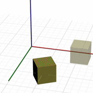
The first image applies a rotate then translate, which rotates the object 45 degrees then moves it to the right (positive X). The second image moves the box, then rotates it. Since it's some distance from the rotation origin, it will spin 450 around the origin.

Example B:
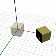
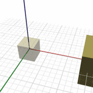
The first image applies a translate, then scale, which will enlarge the box, then move it. The second image will move the box, then scale it using the origin at the center point. Notice how it moves the box further from the origin.

2D in 3D
Explained
One way to really speed up XAML rendering is to render entirely in DirectX without using any GDI calls. Unfortunately, any third-party developer who does not have access to Windows source code has no chance of implementing XAML exactly like Avalon. There are alternative solutions however; one of them being to convert all would-be GDI drawings into triangles for rendering by the 3D pipeline. This process is referred to as triangulation or triangulating from now on. The process of triangulating 2D drawing calls can be complex, and in some cases, slightly slower than GDI. The payoff is when the 2D geometry that has been constructed is not physically changing but is animating a lot using standard transforms. This keeps the graphics process almost entirely on the video card, so the slowness of rendering in 2D (mainly waiting for the image(s) to get to the video card) is mostly avoided. The downside is that the triangulated representation may not look exactly the same as its 2D counterpart, but if speed is your goal, then this may not be an issue.
At the moment, the Mobiform fully DirectX rendering mode is 98% complete. While there are noticeable differences between the same GDI drawing and the DirectX drawing, you can already see the speed difference. In time, the triangulation and rendering should be almost indistinguishable from GDI drawing, and be tremendously faster.
Effective usage
The key to getting the speed increase is to reduce the amount of time spent constructing the triangulated geometry from the GDI drawing. A hugely complex drawing can be slow, but once it’s triangulated, it can be extremely fast. Using transforms to move and rotate a drawing is preferable to animating the properties of a 2D XAML object. For example, you could create a sphere and animate its position, or you could wrap it in a TransformCollection and move it using a translation.
ToDo
- As I mentioned above, using a transform to animate a 2D object helps speed, but might not always be practical. Some work has to be done to internally reduce triangulation when a XAML property has changed but doesn’t physically change the shape. Currently, anytime a property is changed, it is re-triangulated, this is especially slow on text.
- Anti-Aliasing (smooth edges). This is the greatest visible difference between GDI and DirectX rendering pipelines. GDI+ is extremely effective at anti-aliasing whereas DirectX is notoriously bad, especially on plain untextured geometry. Aside from being bad at it, good anti-aliasing in DirectX is not yet widely supported. There are a few options though, and with time and progress in this area, the rendering will soon look very much the same.
- Shapes with holes. Currently, any 2D shapes with holes in it (any text, butterfly.xaml sample) are considerably slowed down by the process of cutting out holes.
- Optimize triangulation. Although the general rule is to avoid this, it has to be done at some point. There’s always room to make it just a little faster.
- New text system. Since it is so slow to triangulate and it usually ends up re-triangulating the same characters repeatedly and entirely, new text system should be made to mimic GDI+ in DirectX.
Conclusion
Hopefully, this has given you a good overview for 3D in XAML and you are ready to start experimenting in Mobiform and or Longhorn. Although the 3D API for Avalon is still early in its development (and will most likely change heavily on the next pre-release), the basics have been covered here, and should at the very least, give you a head start on the next release. It can only get better from here on in.
Jason Wylie. E-mail. Website.
This member has not yet provided a Biography. Assume it's interesting and varied, and probably something to do with programming.


 General
  News
News  Suggestion
  Question
  Bug
Bug  Answer
  Joke
Joke  Praise
  Rant
Rant  Admin
Admin 


