
Controlling Floppy Drive Stepper Motor via Parallel Port
4.92/5 (76 votes)
Dec 9, 2006
10 min read
446328
10205
Controlling a floppy drive stepper motor using computer's parallel port
- Download source files (inpout32.dll required) - 11.2 Kb
- Download demo project (.NET Framework 2.0 and inpout32.dll required) - 4.7 Kb

Warning
The PC parallel port can be damaged quite easily if you make incorrect connections. If the parallel port is integrated to the motherboard, repairing a damaged parallel port may be expensive, and in many cases, it is cheaper to replace the whole motherboard than to repair that port. Your safest bet is to buy an inexpensive I/O card which has a parallel port and use it for your experiment. If you manage to damage the parallel port on that card, replacing it will be easy and inexpensive.
Disclaimer
While every effort has been made to make sure the information in this article is correct, the author cannot be made liable for any damages, whatsoever, for loss relating to use or implementation of this article. Use this information at your own risk.
Introduction
In this article, we will connect a 3½ inch floppy drive to our computer's parallel port and write a program to control its stepper motor. We won't be taking the stepper motor out from the floppy drive because a floppy drive has a built in controller which can be easily used for controlling its stepper motor. The advantages of this are:
- We will not have to worry about making the electronics for controlling the stepper motor.
- Assuming that you can use a recycled floppy drive, this project shouldn't cost you anything. Old, unused floppy drives can be salvaged from junkyards and old computers.
- A good knowledge of electronics is not a prerequisite since we'll only be making a few simple connections.
However, if you have a good background of electronics and you're interested in controlling a stepper motor without the disk drive electronics, read Stepper Motor Control through Parallel Port by Bhaskar Gupta.
Before we begin, I would recommend you to go through I/O Ports Uncensored - 1 - Controlling LEDs (Light Emitting Diodes) with Parallel Port by Levent Saltuklaroglu and be sure to read the sections on Parallel Ports and Hexadecimal / Decimal / Binary if you haven't already done so. Also, make sure that the floppy drive you use is in working order. I've wasted an entire day trying to make a broken one work. It's a waste of time.
Stepper Motors
What they are?
So, what are stepper motors and how are they different from conventional electric motors? Simply put, a stepper motor is a brushless, synchronous electric motor that can divide a full rotation into a large number of steps. Conventional motors spin continuously while a stepper motor moves only one step at a time. Therefore, stepper motors are useful for precise motion and position control.
How they work?

The simplest way to think of a stepper motor is a bar magnet and four coils. When current flows through coil "A" the magnet is attracted and moves one step to the right. Then, coil "A" is turned off and coil "B" turned on. Now, the magnet moves another step to the right and so on…
A similar process happens inside a stepper motor, but the magnet is cylindrical and rotates inside the coils. For a stepper motor to move, these coils should be turned on in the correct sequence. However, we don't have to worry about this since we will be using the floppy drive's built in controller.
The Floppy Cable
The floppy cable is usually a flat, gray ribbon cable similar to the standard IDE cable. The floppy cable has 34 wires (odd colored wire is wire 1). There are normally five connectors on this cable, but some cables, like the ones I'm using, have only three. These connectors are grouped into three sets:
- Controller Connector: This is the single connector on one end of the cable and is used for connecting the floppy disk controller, either on a controller card or the motherboard.
- Drive A connectors: The pair of connectors (or single connector in the case of a three-connector cable) at the opposite end of the cable is for the A: floppy drive.
- Drive B connectors: The pair of connectors (or single connector in the case of a three-connector cable) in the middle of the cable is intended for the B: floppy drive.
An image from The PC Guide illustrates:

3.5" Drive Connector pin-out
![]()
| Pin # | Function |
| Odd pins (e.g. 1, 3, 5 etc) | Ground |
| 2 | High Density Select |
| 8 | Index Pulse (produced by the spindle motor for timing) |
| 10 | A: Motor on |
| 12 | Drive select B: |
| 14 | Drive select A: |
| 16 | B: Motor on |
| 18 | Direction of movement of the stepper motor |
| 20 | Step Pulse |
| 22 | Write Data |
| 24 | Write Enable (a Low turns on the write circuit) |
| 26 | Track 0 (a Low puts the head stepper over track zero) |
| 28 | Write Protect |
| 30 | Read Data |
| 32 | Select head (a Low selects head zero) |
| 34 | Disk Change Switch |
Floppy Power Connector

Pin-out
| Pin # | Color | Description |
| 1 | Red | +5 V |
| 2 | Black | +5 V Ground |
| 3 | Black | +12 V Ground (Same as +5 V Ground) |
| 4 | Yellow | +12 V |
Note
Some connectors might supply only two wires, usually the +5 V and a ground pin. This is because the floppy drives in most new systems run only on +5 V and do not use the +12 V at all.
Making the connections
This part is really easy. All you need are:
- A parallel port cable
- A floppy cable
- 3 short single core wires (for connecting the floppy drive connector to the parallel port)
- A screwdriver (for opening the outer cover of the floppy drive)
- A multimeter for continuity testing (not essential but if you want to test your connections, this can be really helpful)
- A floppy drive (duh!)


Connect the 3.5" Drive "A" Connector on your floppy cable to your floppy drive. Now, make sure your computer's off and unplugged. Open your computer and take out the floppy power connector. Carefully plug this connector to your floppy drive. Reversing the red and yellow wires could fry your floppy drive. You'll see five notches on the power connector. They should point upward when they're installed. Fortunately, these connectors are keyed and therefore difficult to insert incorrectly. Check out the picture below:

Note
If you want, you can extend the power connector cord so that the floppy drive can reside outside the PC case. Just cut the wires (1 red, 1 yellow, 2 black) and patch in a couple feet. There's no need to extend the yellow wire since it carries +12 V, which will not be used by the floppy drive. As you can see in the picture above, I've only extended 1 red and 1 black.
Now, take the motherboard end of the floppy cable and follow the instructions below to connect it to the parallel port cable. Here's a diagram I've made to show the connections:

Parallel Port Floppy Cable Connector
Pin # 2 (D0)------> Pin # 20 (Step Pulse)
Pin # 3 (D1)------> Pin # 18 (Direction)
Pin # 14 --> Ground (Drive Select A:)
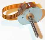
Here's a picture of the connections I made:

I was using a defective parallel port cable and so my parallel port pins are in reverse order. Don't let that confuse you. Just go with the diagram.
Finally, connect the other end of the parallel port cable to your computer. That's it! Make sure all your connections are correct and there are no short circuits.
Writing the code
It's time to write some code. This is a fun and tricky part. It's tricky because even a small bug in your program could prevent the stepper motor from moving. I have used inpout32.dll for interoping. Download it from http://www.logix4u.net/inpout32.htm [^]. After downloading it, put it in your System32 folder and import it into your project:
using System;
using System.Runtime.InteropServices;

private class PortAccess
{
    [DllImport("inpout32.dll", EntryPoint="Out32")]
    public static extern void Output(int address, int value);
}
For sending values to our parallel port, we'll be using PortAccess.Output. This method takes in two parameters, address and value. For knowing your parallel port address, go to Control Panel > System > Hardware > Device Manager > Ports (COM & LPT) > Printer Port (LPT1) > Properties > Resources > Resource Settings. Here, you'll see the address of your parallel port. Mine is "0378 – 037F". This is in hexadecimal form. 0x378 (Hexadecimal) = 888 (Decimal). If you are using LPT2, your address would probably be "0x278" (Decimal equivalent is 632).
For moving the stepper motor, we will have to pulse pin 20 on the floppy drive connector. The direction of movement will depend on the high/low state of pin 18. Now, since pins 20 and 18 are connected to pins 2 (D0) and 3 (D1) on the parallel port, pulsing pin D0 will move the stepper motor and its direction will depend on the high/low logical state of D1. So, here's a sample code for moving the stepper motor 10 steps in one direction:
for (int i = 0; i < 10; i++)
{
    PortAccess.Output(888, 1);
    System.Threading.Thread.Sleep(50); // Delay
    PortAccess.Output(888, 0);
    System.Threading.Thread.Sleep(50); // Delay
}
I'm sending the values 1 and 0.
1 (Decimal) = 0001 (Binary)
0 (Decimal) = 0000 (Binary)
Here, I'm changing the high/low state of D0 but I'm keeping D1 constantly low. Therefore, the stepper motor will move 10 steps in one direction.
Notice that I'm delaying the execution of the code after sending a value. This delay is needed to provide enough time for the magnetic field inside the coils to build up and move the magnet. Without this delay, the coils will switch on and off so fast that the magnet wouldn't move.
To move the stepper in the other direction, send the values 3 and 2:
for (int i = 0; i < 10; i++)
{
    PortAccess.Output(888, 3);
    System.Threading.Thread.Sleep(50); // Delay
    PortAccess.Output(888, 2);
    System.Threading.Thread.Sleep(50); // Delay
}
3 (Decimal) = 0011 (Binary)
2 (Decimal) = 0010 (Binary)
Here, I'm changing the high/low state of D0 but I'm keeping D1 constantly high.
In future, if you plan to use pins other than D0 and D1, always make sure that the values you send are correct. The Windows Calculator can be helpful for performing binary to decimal conversions.

The first time I tried controlling a floppy drive stepper motor, I chose wrong values and my stepper wouldn't budge! I was checking the connections over and over but I had no clue that the problem was in my program! I wasted at least two days because of this.
Well, here's a screenshot of my 'working' application:

Conclusion
We have reached the end of this article. I hope you enjoyed it and successfully controlled your floppy drive stepper motor. Now what? Just let your imagination go wild!! Stepper motors can be used to perform a variety of small tasks which require precise motion/position control (for e.g. in robotics). I used mine to pan a camera! Check it out on my blog: http://ashishrd.blogspot.com/2006/11/camera-panning-using-parallel-port.html[^]. If you end up making something interesting, I'd love to hear about it. Happy coding!!
History
- 16-Mar-2007 - Added photo credits
- 21-Dec-2006 – Minor corrections
- 09-Dec-2006 – Initial publication