.
1.
Introduction
Long time ago I had had one idea related to mechanics. Lots of engineering problems
requires simulation of aggregates. Mechanics of one object of aggregate may be simple.
However equation of all aggregate may be very complicated. For example
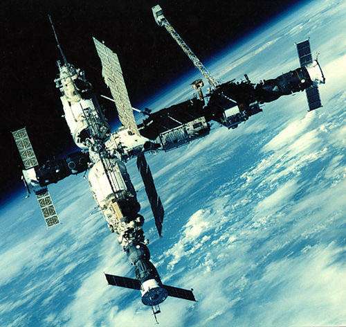
the picture of
the beginning of this article shows the Mir
orbital station. This station has nonrigid
photovoltaics, gyroscopes and/or
flywheels, jet engines
etc. Long time ago I had an idea to develop designer of aggregates from those components.
However implementaion of this idea only would provide a little advantage. Space
objects have many aspects that lay outside pure mechanics. For example they
interact with Magnetic fields. Motion of space object depends of this
interacion. Moreover space objects have many devices founded on different physical
principles and related to those motion. Now I have an universal framework and I
can develop a valuable designer. But now I'm not engaged by mechanics of aggregates
and maybe
I'll never be occupied by this subject. However I wish to prove that this
framework is really universal. Dynamics of aggregates is an excellent confirmation
of the framework universality. So I've developed a few code devoted to this subject. Mybe
this code contains lots of bugs. However the main idea is right.
2.
Background
Dynamics of aggregates may be described by
Classical mechanics that is familiar to any engineering student. How to
create equation of aggregate from equations of its components. Elements of aggregates
are connected. According to Classical mechanics first element acts to second by the
invetred force and momenum that second acts to first. Moreover position and orientation
of connections of two elements should coincide. Using listed above conditions we
can create motion equations. I'll not overload readers here by technilal details
but I'll write a paper to one of scietific journal later.
3. Simple example
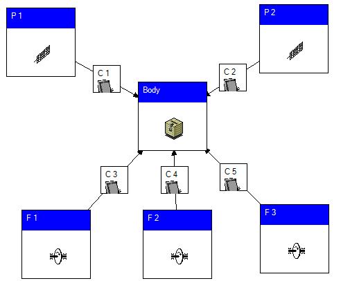
Let us consider the following example of usage of the framework for simulation of
dynamics of aggregates. This example contains spacecraft with 5 connections
C 1, ..., C 5. Flywheels F 1, F 2,
F 3 and photovoltaics P 1, P 2,
P 3 are connected to spacecraft (See picture below)

Excuse me for my bad painting.This situation may be simulated by the
following way.
If we open property editor of connection C 4 then we have:
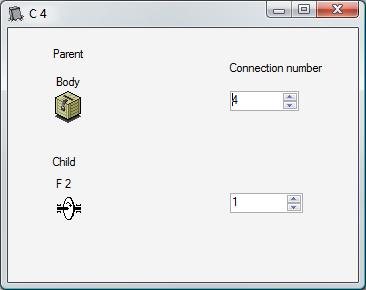
This picture has the following meaning. The F 2 flywheel is connected
to connection place 4 of the Body. Flywheel has a single connection
numbered by 1. We need a library of objects for simulation of aggregate dynamics.
4. Library of objects
Library of objects has been developed as separated dll. Its present version contains
three types of objects:
- rigid body;
- flywheel;
- elastic vibrations body.
For using these objects you should put an
 object to desktop. Then open AggregateLibrary.dll and select type of object
by the following way:

Let us consider features of these objects.
4.1 Rigid body
Rigid body is a simplest object of 6D dynamics. My implementation of rigid body
contains following editor of properties:

Key properties of my rigid body are places of connetions. Connections are defined
by those coordinates and orientation. The rigid body that is presented above has
5 connections. You can define those coordinates X, Y, Z and components Q0, Q1, Q2,
Q3 of quaternions of orientation. Rigid body also has another properties. We will
consider them below.
4.2 Flywheel
Flywheel has general properties of rigid body and additional ones. Additional properties
of flywheel include:
4.3 Elastic vibrations body
Elastic vibrations body is a mechanical system of infinite degrees of freedom. Usually
math model of this object contains finite degrees of freedom with finite set of
valuable harmonic oscillations.
Every harmonic oscillation may be described by following second order system of
ordinary differential equation:

Where q is generalized coordinate and Q is generalized force.
Editor of properties of this object is presented below

This object contains 5 valuable harmonic oscillations. You can edit coefficients
of differential equations of these oscillations.
5. Advanced examples
Main advantage of this framework is interoperabilty with different brunches of science
and engineering. These examples show this advantage of the framework. These
examples are rather popular than realistic ones. Realistic pictures are much more
complicated.
5.1 Controlled spacecraft
Let us consider following example. We have a spacecraft.

Currents of its equipment interacts with
Earth's magnetic field. Spacecraft has a photovoltaic that is an elastic vibrations body. It is used a flywheel for angular stabilzation of the spacecraft.
Now let us construct this situation:

Now I'll explain it. First of all I setup Coordinates of Spacecraft.
We need it for definition of gravitational acceleration and magnetic field. Then
I construct Magnetic Field by formulas.
Earth's magnetic field is very complicated and it is not easy to construct
it by formulas. Usage of external library is more appropriate. But now I've no such library and I set formulas from my mind. It is convenient to have a vector of magnetic
field. Therefore I've used Field Vector:
 i
i
I've named this operation as assembly. Using vector I've defined mechanical moment
of field spacecraft interaction as vector product of
magnetic induction and magnetic
moment of spacecraft:

This product is contained in Magnetic force. Then we disassembly
result vector using the Force components. Unlike magnetic field
I have got a library of gravity field (square Gravity). I've used
it for definition of gravity accelerations. Now we've defined all forces and we
can put Spacecraft and define its properties. They are exhibited on the following
form:

Using aliases we've linked Coordinates and Spacecraft.
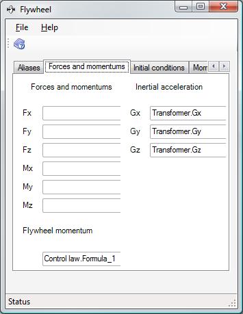
The tab page of forces and moments is presented below:
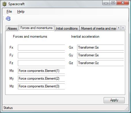
We've defined inertial accelerations and mechanical moments. Then we connect a
Flywheel and a Photovoltaic to Spacecraft
and define those properties. Now the mechanical system is ready. Let us construct
its control system. First
its element is a sensor. We will
use a sensor of local vertical. To do this we define Spacecraft frame
and Earth's center frame. Relative position (6D)
enables us simulate the sensor of local vertical. The Control law
uses it. And at last Flywheel moment of Flywheel is a Formula_1
of Control law:
This system is unstable. If you have 5 minutes only then it is not easy to construct
the control system of spacecraft. It is my first experience. Maybe it is the last
one. To say true, I can do nothing. My mission is to explain to specialists the most nontrivial aspects of their occupation.
5.2 Virtual vibrostand
At part 3
I had had performed a lot of work. I had made a frequency difference detector and
a phase discriminator. This work should be used for mechanics. Now I'll use this
work for definition of frequency
response. To do this I'll construct virtual vibrostand. I'd never seen real
vibrostand. However I think that it looks like:

Mechanical device acts to spacecraft by momentum and then computer compares input
and output signals. Now I'll construct this vibrostand using the framework, spacraft
of 5.1 and schemes of
part 3 :

The Chirp acts by momentum on spacecraft. The
Chirp rate is small. Another parts of this scenario are parts of frequency
difference detector and phase discriminator. Amplitude and
Phase are components of
frequency response. However it is not worth to try it since this spacecraft
is unstable
6.
Points of interests
OMG I've got this idea off my brain. Now I can devote myself to more interesting
things.
