Introduction
In this brief article we generate a pulse width modulation signal for a servomotor control with VHDL.
Background
First of all, a servomotor is nothing more than a direct current motor with an electronic circuit attached in order to achieve better control. For such control, we need to generate a waveform like the one shown below:

The time, or frequency, of the pulse determines the position of the servo. Each servo has its own range of frequencies, given by the manufacturer in the data sheet. The figure shows values within 1 and 2 ms.
Design of the control
The control signal for the servomotor is made out of two frequencies:
- Refresh frequency, of 20ms.
- Pulse width range, provided by the manufacturer. For this article, we are going to assume such frequency goes from 0.5ms to 2.5ms.
First of all, we need to find our range of operation, given by:
Now we need to know the resolution for the servo, which is the quantity of position it can take. Therefore, the minimum needed frequency is equivalent to:
If our servomotor can take up to 128 position, we yield:
We now need a frequency divider of 64kHz. Although we can do one following the process described at frequency divider with VHDL, here we have the full code of the divider from 50MHz to 64kHz:
library IEEE;
use IEEE.STD_LOGIC_1164.ALL;

entity clk64kHz is
    Port (
        clk    : in  STD_LOGIC;
        reset  : in  STD_LOGIC;
        clk_out: out STD_LOGIC
    );
end clk64kHz;

architecture Behavioral of clk64kHz is
    signal temporal: STD_LOGIC;
    signal counter : integer range 0 to 780 := 0;
begin
    freq_divider: process (reset, clk) begin
        if (reset = '1') then
            temporal <= '0';
            counter  <= 0;
        elsif rising_edge(clk) then
            if (counter = 780) then
                temporal <= NOT(temporal);
                counter  <= 0;
            else
                counter <= counter + 1;
            end if;
        end if;
    end process;

    clk_out <= temporal;
end Behavioral;
Finally, we know that with a 64kHz clock we will have 1ms each 64 iterations. So, in order to have a frequency of 20ms, we only need to multiply 20 * 64, which will be implemented with a counter from 0 to 1279.
Implementation in VHDL
For the VHDL implementation we have three inputs: 64 kHz clock, reset, and a vector that an take the values from 0 to 127. The only output is the servomotor control signal. The code is shown below.
library IEEE;
use IEEE.STD_LOGIC_1164.ALL;
use IEEE.NUMERIC_STD.ALL;

entity servo_pwm is
    PORT (
        clk   : IN  STD_LOGIC;
        reset : IN  STD_LOGIC;
        pos   : IN  STD_LOGIC_VECTOR(6 downto 0);
        servo : OUT STD_LOGIC
    );
end servo_pwm;

architecture Behavioral of servo_pwm is
    -- Counter, from 0 to 1279.
    signal cnt : unsigned(10 downto 0);
    -- Temporal signal used to generate the PWM pulse.
    signal pwmi: unsigned(7 downto 0);
begin
    -- Minimum value should be 0.5ms.
    pwmi <= unsigned('0' & pos) + 32;
    -- Counter process, from 0 to 1279.
    counter: process (reset, clk) begin
        if (reset = '1') then
            cnt <= (others => '0');
        elsif rising_edge(clk) then
            if (cnt = 1279) then
                cnt <= (others => '0');
            else
                cnt <= cnt + 1;
            end if;
        end if;
    end process;
    -- Output signal for the servomotor.
    servo <= '1' when (cnt < pwmi) else '0';
end Behavioral;
The signal cnt is used to implement the counter from 0 to 1279, which is described from lines 22 to 33.
The input signal pos is a vector that can take any value from 0 to 127, which yield the range of 0ms to 2ms. Since we need a signal that goes from 0.5ms to 2.5ms, we need to add an offset of 32 equivalent to the 0.5ms.
The listing 3, shown below, describes the PORT MAP needed to glue together the frequency divider and the servomotor control component.
library IEEE;
use IEEE.STD_LOGIC_1164.ALL;

entity servo_pwm_clk64kHz is
    PORT(
        clk  : IN  STD_LOGIC;
        reset: IN  STD_LOGIC;
        pos  : IN  STD_LOGIC_VECTOR(6 downto 0);
        servo: OUT STD_LOGIC
    );
end servo_pwm_clk64kHz;

architecture Behavioral of servo_pwm_clk64kHz is
    COMPONENT clk64kHz
        PORT(
            clk    : in  STD_LOGIC;
            reset  : in  STD_LOGIC;
            clk_out: out STD_LOGIC
        );
    END COMPONENT;

    COMPONENT servo_pwm
        PORT (
            clk   : IN  STD_LOGIC;
            reset : IN  STD_LOGIC;
            pos   : IN  STD_LOGIC_VECTOR(6 downto 0);
            servo : OUT STD_LOGIC
        );
    END COMPONENT;

    signal clk_out : STD_LOGIC := '0';
begin
    clk64kHz_map: clk64kHz PORT MAP(
        clk, reset, clk_out
    );

    servo_pwm_map: servo_pwm PORT MAP(
        clk_out, reset, pos, servo
    );
end Behavioral;
Test bench and simulation
For the test bench, we use five different values for pos, described from lines 43 to 59.
LIBRARY ieee;
USE ieee.std_logic_1164.ALL;

ENTITY servo_pwm_clk64kHz_tb IS
END servo_pwm_clk64kHz_tb;

ARCHITECTURE behavior OF servo_pwm_clk64kHz_tb IS
    -- Unit under test.
    COMPONENT servo_pwm_clk64kHz
        PORT(
            clk   : IN  std_logic;
            reset : IN  std_logic;
            pos   : IN  std_logic_vector(6 downto 0);
            servo : OUT std_logic
        );
    END COMPONENT;

    -- Inputs.
    signal clk  : std_logic := '0';
    signal reset: std_logic := '0';
    signal pos  : std_logic_vector(6 downto 0) := (others => '0');
    -- Outputs.
    signal servo : std_logic;
    -- Clock definition.
    constant clk_period : time := 10 ns;
BEGIN
    -- Instance of the unit under test.
    uut: servo_pwm_clk64kHz PORT MAP (
        clk => clk,
        reset => reset,
        pos => pos,
        servo => servo
    );

   -- Definition of the clock process.
   clk_process :process begin
        clk <= '0';
        wait for clk_period/2;
        clk <= '1';
        wait for clk_period/2;
   end process;

    -- Stimuli process.
    stimuli: process begin
        reset <= '1';
        wait for 50 ns;
        reset <= '0';
        wait for 50 ns;
        pos <= "0000000";
        wait for 20 ms;
        pos <= "0101000";
        wait for 20 ms;
        pos <= "1010000";
        wait for 20 ms;
        pos <= "1111000";
        wait for 20 ms;
        pos <= "1111111";
        wait;
    end process;
END;
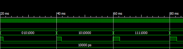
The result of the simulation is shown below. The following frequencies were obtained:
- A refresh frequency of 19.9936 ms.
- A minimum frequency of 0.4920 ms.
- A maximum frequency of 2.4835 ms.


 General
  News
News  Suggestion
  Question
  Bug
Bug  Answer
  Joke
Joke  Praise
  Rant
Rant  Admin
Admin 


