Introduction
When all the screen elements are fixed, you can look at the program only through the eyes of its developer and go only in his
steps. When all the screen elements are movable and resizable, you can do all the things that were coded by the developer but you can do all those things in
the way you want them to be done. This is the power of user-driven applications. To get all those possibilities, you need only one small
change in the program: all the screen elements must be easily movable and resizable
by you at any moment.
In the first part of this article I wrote only about the small colored spots, segments of straight lines, and often used elements
based on straight lines – polygons. My algorithm of turning any screen object into movable / resizable is based on covering an object by the nodes of only
three types: circles, curved strips, and convex polygons. The available set of nodes looks very limited but the examples from part one of this article demonstrate
that this limited set of nodes allows to move, resize, and reconfigure such very popular objects as polygons. The variety of elements used in our programs
is not limited to rectangles or even polygons. There are many different objects and many of them have not the straight but curved borders. To turn any screen object
with the curved border into movable something interesting and not so obvious must be done and the first step was the invention of the N-node covers.
The set of examples for this article is only a small subset of examples from the book World of Movable Objects. They are not
the exact copy of those examples; they are combined and modified; the book includes much more very interesting examples which are not going to appear
here. The book with its accompanying project and several other very helpful documents and projects can be downloaded from
the http://sourceforge.net/projects/movegraph/files/?source=directory
Even such a small application as the one to accompany this article must be designed as a real user-driven application. Before
starting further explanation, I want to remind the rules of such applications; all these rules are implemented in the accompanying program.
- All the elements are movable.
- All the parameters of visibility are
easily controlled by the users.
- The users’ commands on moving /
resizing of objects or on changing the visibility parameters are implemented
exactly as they are; no additions or expanded interpretation by developer are
allowed.
- All the parameters are saved and
restored.
- The above mentioned rules are
implemented at all the levels beginning from the main form and up to the
farthest corners.
I always underline that the main feature of
user-driven applications (or the main problem of designing such applications)
is the easy to use technique of turning any screen element into movable /
resizable. Just now when I have the same algorithm for moving and resizing of
objects this looks normal and absolutely logical. But it was not so from the
beginning. There were two separate tasks: to provide movability and
resizability. I started my work with the rectangles and for those rectangular
graphical objects both tasks were solved with the nodes of three mentioned
shapes. Circular nodes were in the corners of rectangles and provided their reconfiguring;
rounded strips were along the straight borders and provided resizing; polygonal
node covered the main area and provided the movement of the whole object.
When I turned my attention from rectangles to the
circular graphs, their movability was easily provided with a single circular
node. The problem was with the resizing of circles. None of the used nodes
can be bent so none of them can cover the border of a circle and provide its
resizing. I didn’t want to add nodes of different shapes because this would be
definitely a wrong solution. In this way the new shape of an object will
always require the new shape of a node – this is a wrong decision. The
solution came by using absolutely new technique: to cover the curved border not
by one or few nodes of the new shape but by the big number of the small
standard nodes that together reproduce a narrow strip along the border of an arbitrary
shape.
Let us analyse the difference between the standard
design of covers and the new technique. The standard technique declares that
the number of nodes in the cover depends only on the shape of an object; the
examples from the first part of this article and from the book World of
Movable Objects perfectly demonstrate this rule.
- Cover for any segment of a straight line does not depend on the length of the segment and
always consists of three nodes: two circular nodes on the end
points and a single strip node based on these two points.
- Cover for any rectangle consists of nine nodes: four circles on the corners, four strips along
the segments of the border, and one rectangular node for the whole area.
- The number of nodes in the cover for a
chatoyant polygon linearly depends on the number of vertices. If
there are M vertices in the polygon, then there are M circular nodes on
vertices, one circular node on the central point, M strip nodes between
the neighboring vertices, and M triangular nodes to cover the area of a
polygon. Thus, for any polygon of such type with M vertices we have a
cover consisting of (3 * M + 1) nodes.
Because the number of nodes in the standard cover is
usually small, then the behaviour of each node is very individual and there is
a specific piece of code for each node in the MoveNode() method.
The new technique for the objects with the curved
borders changes some of the basic rules of cover design. For such objects the
number of nodes in the cover depends not on the shape of an object but on its
size. As you will see in the next example, for a circle this number depends on
the radius of a circle. Because we need the resizable objects and the number
of nodes in the cover to provide such resizability depends on the size of an
object at each particular moment, then the number of nodes changes throughout
the life of an object. This is the main feature of the new covers. There is
often a significant (maybe huge) number of nodes in such covers and because of
this I call them the N-node covers.
For a big object, the number of nodes can go into
hundreds and it would be a real problem if each of them would need its personal
and specific code in the
MoveNode() method. It will be impossible
to write such method for hundreds of nodes or at least it will be impracticable.
Instead of infinitive lines of code, the classes of objects with the N-node
covers demonstrate very simple MoveNode() methods. It
happens because the behaviour of all those nodes is identical and it is described
by very simple code. The behaviour of each particular node (the reaction on
its movement) does not depend on the particular number of the pressed node but it
is the same for all the nodes of the group even if there are dozens or hundreds
of such nodes.
The best object to introduce the N-node covers is
a circle. A circle is a very simple element but even with it there are
variants so I am going to demonstrate three different examples with the
circles.
Circles
- File: Form_Circles_ClassicalCover.cs
- Menu
position: Circles – Classical N-node cover
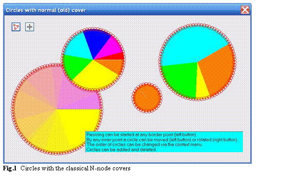
Let us start with the classical case of the
multicolored circles which can be resized by any border point and moved forward
or rotated by any inner point. Our movable / resizable circle of the Circle class is defined by the central point, the radius of a
circle, and the set of values associated with the sectors. Each sector can be
painted by its own color; the existence of many colors makes the rotation more
obvious. It is possible to have a single color for the whole circle and for
such case an auxiliary line is painted on the circle; without this line the
rotation of the uncolored circle is not detected by our eyes.
public class Circle : GraphicalObject
{
PointF m_center;
float m_radius;
double m_angle;
int nNodesOnCircle;
double [] vals;
double [] sweep;
List<Color> clrs = new List<Color> ();
Rotation dirDrawing;
The border of a circle is covered by a set of small
circular nodes; these nodes are positioned not side by side but the
neighbouring nodes overlap (figure 1). Thus we receive along the border
a sensitive strip of nodes with the varying width. The radius of each small
circular node is five pixels (nrSmall = 5) and the
distance between the centers of the neighbouring nodes is not bigger than eight
pixels (distanceNeighbours
= 8). With such numbers, the width of
our sensitive strip is never less than six pixels. I think that such strip is
wide enough to press the border for resizing. The number of nodes along the
border of the circle – nNodesOnBorder – is determined by the radius of the circle and the
distance between the neighbouring nodes.
private void NodesOnBorder ()
{
    nNodesOnBorder =
            Convert .ToInt32 ((2 * Math .PI * m_radius) / distanceNeighbours);
}
The cover of a Circle object consists of the small circular nodes along the border plus one
big circular node to cover the whole area of an object; this big node is the
last one in the cover.
public override void DefineCover ()
{
    CoverNode [] nodes = new CoverNode [nNodesOnBorder + 1];
    for (int i = 0; i < nNodesOnBorder; i++)
    {
        nodes [i] = new CoverNode (i, Auxi_Geometry .PointToPoint (m_center,
                       2 * Math .PI * i / nNodesOnBorder, m_radius), nrSmall);
    }
    nodes [nNodesOnBorder] = new CoverNode (nNodesOnBorder, m_center, m_radius,
                                            Cursors .SizeAll);
    cover = new Cover (nodes);
    cover .SetClearance (false);
}
By default the circle with the smooth color change from
yellow to violet in the bottom left corner of figure 1 has the radius of
130 pixels; thus, there are slightly more than 100 nodes along its border. It
would be impossible to write separate code for moving each of these nodes and
it is not needed at all. There is a special reaction on moving the big
circular node – the last one in the cover – but there is no code depending on
the number of any other node. Instead there is the same reaction on moving any
other node.
When any small node on the border is pressed for
moving, then the cursor is moved exactly on the border by calling the Circle.StartResizing()
method. (One general remark on the code
of the StartResizing() methods for all the
classes. In order to make the code consistent with similar methods from the
book, whenever there are two parameters for the StartResizing() method, then the first one is the cursor location and
the second one is the node number. Pay attention that there was the wrong
order of parameters in some classes used in the first part of this article; now
that code is corrected.)
private void OnMouseDown (object sender, MouseEventArgs e)
{
    ptMouse_Down = e .Location;
    if (mover .Catch (e .Location, e .Button))
    {
        GraphicalObject grobj = mover .CaughtSource;
        if (grobj is Circle)
        {
            Circle circle = grobj as Circle;
            if (e .Button == MouseButtons .Left)
            {
                if (mover .CaughtNode != circle .NodesCount - 1)
                {
                    circle .StartResizing (e .Location, mover .CaughtNode);
                }
            }
            else if (e .Button == MouseButtons .Right)
            {
                circle .StartRotation (e .Location);
            }
        }
    }
    ContextMenuStrip = null;
}
This Circle.StartResizing() method not only places the cursor exactly on the
border (ptOnBorder) but also calculates two points – ptNearestToCenter and
ptFarAway – between which
the mouse can be moved until its release.
public void StartResizing (Point ptMouse, int iNode)
{
    double angleBeam = Auxi_Geometry .Line_Angle (m_center, ptMouse);
    PointF ptOnBorder = Auxi_Geometry.PointToPoint (m_center, angleBeam, m_radius);
    Cursor .Position = form .PointToScreen (Point .Round (ptOnBorder));
    ptNearestToCenter =
                      Auxi_Geometry .PointToPoint (m_center, angleBeam, minRadius);
    ptFarAway = Auxi_Geometry .PointToPoint (m_center, angleBeam, 4000);
}
From now on until the release of the mouse, the cursor
position is used as the exact place of the border. As you can see from the
code of the Circle.MoveNode() method,
the number of the pressed node on the border does not matter at all and only
the mouse position (ptM) matters.
public override bool MoveNode (int i, int dx, int dy, Point ptM,
                                   MouseButtons catcher)
{
    bool bRet = false;
    if (catcher == MouseButtons .Left)
    {
        if (i == nNodesOnBorder)
        {
            Move (dx, dy);
        }
        else
        {
            PointF ptBase, ptNearest;
            PointOfSegment typeOfNearest;
            Auxi_Geometry .Distance_PointSegment (ptM, ptNearestToCenter,
                      ptFarAway, out ptBase, out typeOfNearest, out ptNearest);
            Cursor .Position = form .PointToScreen (Point .Round (ptNearest));
            m_radius = Convert .ToSingle (Auxi_Geometry .Distance (m_center,
                                                                   ptNearest));
            bRet = true;
        }
    }
    else if (catcher == MouseButtons .Right)
    {
        double angleMouse = Auxi_Geometry .Line_Angle (m_center, ptM);
        m_angle = angleMouse - compensation;
        bRet = true;
    }
    return (bRet);
}
The cover depends on the size of the circle but it is not changed during the process of resizing. Only at the last moment of resizing when the border is released,
the Circle.StopResizing() method is called.
private void OnMouseUp (object sender, MouseEventArgs e)
{
    ptMouse_Up = e .Location;
    double dist = Auxi_Geometry .Distance (ptMouse_Down, ptMouse_Up);
    int iWasObject;
    if (mover .Release (out iWasObject, out iNodePressed))
    {
        GraphicalObject grobj = mover .WasCaughtSource;
        if (e .Button == MouseButtons .Left)
        {
            if (grobj is Circle)
            {
                Circle circle = grobj as Circle;
                if (iNodePressed != circle .NodesCount - 1)
                {
                    circle .StopResizing ();
                    Invalidate ();
                }
               }
        }
        … …
In the Circle.StopResizing() method the new number of nodes is calculated and the
new cover is designed.
public void StopResizing ()
{
    NodesOnBorder ();
    DefineCover ();
}
The technique demonstrated with the Circle class is the classical case of using N-node covers.
For years I used such technique for different objects with the curved borders;
several examples can be seen in the book World of Movable Objects. But
with the circles a very interesting thing happened not too long ago. I always
thought that such N-node cover was the only way to make circles resizable by
any border point and only last year I understood that there was another, much
easier, and really elegant cover for resizable circles. This new cover is
definitely not the N-node cover as it consists of only two nodes. A circle
must be movable and resizable so the cover has to contain at least two nodes. Here
is the cover designed of exactly two nodes and such primitive cover allows all
the needed movements. When I understood the simplicity and elegancy of this
cover, I began to laugh at myself because for several years I didn’t even think
about such a possibility. The next example demonstrates the circles with this
new cover.
- File: Form_Circles_SimpleCover.cs
- Menu
position: Circles – Simplified cover
Figure 2
demonstrates that the cover for any circle of the Circle_SimpleCover class does not depend on the size of an object and always
consists of only two nodes. Both nodes are big circles and there is a small
difference between them. The first node is a bit smaller than the object while
the second node is slightly bigger than the object. Only the outer part of the
second node is not covered by the first node; this narrow ring surrounds the
border and allows the resizing of a circle.
public override void DefineCover ()
{
    CoverNode [] nodes = new CoverNode [] {
                new CoverNode (0, Center, Radius - delta, Cursors .SizeAll),
                new CoverNode (1, Center, Radius + delta)};
    cover = new Cover (nodes);
    cover .SetClearance (false);
}

Everything else in the Circle and Circle_SimpleCover classes is identical and without visualization of the covers you will
never detect the difference between them. Now I can understand why for several years I didn’t see the possibility of such elegant solution: it is so simple
that even impossible to imagine. The curved borders usually require some knowledge of geometry and a bit of additional calculations. As a rule it is easier to
organize the movability of an object with the straight borders because there are fewer nodes and less calculations. In the case of a circle it turned out
that there is a solution which can’t be simpler even theoretically: for movable and resizable object it is impossible to have less than two nodes.
In organizing its movability and resizability, a circle turned out to be simpler than a segment of a line. Unbelievable but real result.
There is a positive side in not finding this elegant
solution from the beginning: without it I had to invent the technique of N-node
covers which is very helpful in many cases.
- File: Form_Circles_SlidingPartitions.cs
- Menu
position: Circles – With sliding partitions
There is one more example of circles. Moving and resizing of these multicolored circles are organized in exactly the same
way as in the previous example, but they also allow to move the partitions between the neighbouring sectors. Covers of such circles are demonstrated at figure 3.
The standard rule of cover design requires that smaller nodes must precede the bigger nodes, so in the case of the
Circle_SlidingPartitions class we have the same two big circular nodes as in the previous
Circle_SimpleCover class but before them
we need to include the strip nodes covering all the borders between the neighbouring sectors.
public override void DefineCover ()
{
CoverNode [] nodes;
int nStrips = vals .Length;
nodes = new CoverNode [nStrips + 2];
double angleLine = m_angle;
for (int i = 0; i < nStrips; i++)
{
nodes [i] = new CoverNode (i, m_center,
Auxi_Geometry .PointToPoint (m_center, angleLine, m_radius));
angleLine += sweep [i];
}
nodes [nStrips] = new CoverNode (nStrips, Center, Radius - delta,
Cursors .SizeAll);
nodes [nStrips + 1] = new CoverNode (nStrips + 1, Center, Radius + delta);
cover = new Cover (nodes);
cover .SetClearance (false);
}
The only new part in the Circle_SlidingPartitions class is the moving of borders between the segments so
let us analyse only the code associated with such movement.
There is a restriction on squeezing a circle; this
restriction prevents an accidental disappearance of a circle; the limit on
moving the border in the direction of the central point is calculated inside
the
StartResizing() method which is called
when any border point is pressed. There is an analogous situation when any
border between the sectors is pressed for moving.
Any border between two sectors can be moved in
direction of one neighbour or another. If you move the caught border up to the
next one then the sector between them will disappear and there is no indication
that there is some hidden sector. To avoid such situations, two borders cannot
be positioned at the same angle; there is a minimal angle of 0.05 radian for
any sector. When any strip node is pressed it can be only the node on the
border between two sectors and then the Circle_SlidingPartitions.StartResectoring()
method is called.
private void OnMouseDown (object sender, MouseEventArgs e)
{
  ptMouse_Down = e .Location;
  if (mover .Catch (e .Location, e .Button))
  {
      GraphicalObject grobj = mover .CaughtSource;
      if (grobj is Circle_SlidingPartitions)
      {
          Circle_SlidingPartitions circle = grobj as Circle_SlidingPartitions;
          if (e .Button == MouseButtons .Left)
          {
              if (mover .CaughtNodeShape == NodeShape .Strip)
              {
                  circle .StartResectoring (mover .CaughtNode);
              }
              else if (mover .CaughtNode == circle .Values .Length + 1)
              {
                  circle .StartResizing (e .Location);
              }
          }
          else if (e .Button == MouseButtons .Right)
            {
              circle .StartRotation (e .Location);
          }
      }
  }
  ContextMenuStrip = null;
}
Several values are calculated in the Circle_SlidingPartitions.StartResectoring() method; these values are needed throughout the movement of the caught partition.
- Only two sectors on the sides of the moving
partition are going to change throughout the movement; the numbers of
these sectors are
iSector_Clockwise and iSector_Counterclock. - The range for possible change of the partition’s
angle is limited by values
min_angle_Resectoring and max_angle_Resectoring. - Other sectors are not going to change so the sum
of angles of these two sectors –
two_sectors_sum_values – is not changing throughout the movement of
partition.
public void StartResectoring (int iNode)
{
    iBorderToMove = iNode;
    double angleCaughtBorder = m_angle;
    for (int i = 0; i < iBorderToMove; i++)
    {
        angleCaughtBorder += sweep [i];
    }
    if (dirDrawing == Rotation .Clockwise)
    {
        iSector_Clockwise = iBorderToMove;
        min_angle_Resectoring = angleCaughtBorder + sweep [iSector_Clockwise];
        iSector_Counterclock = (iSector_Clockwise == 0) ? (vals .Length - 1)
                                                   : (iSector_Clockwise - 1);
        max_angle_Resectoring =
                             angleCaughtBorder – sweep [iSector_Counterclock];
    }
    else
    {
        iSector_Counterclock = iBorderToMove;
        max_angle_Resectoring = angleCaughtBorder+sweep [iSector_Counterclock];
        iSector_Clockwise = (iSector_Counterclock == 0) ? (vals .Length - 1)
                                               : (iSector_Counterclock - 1);
        min_angle_Resectoring = angleCaughtBorder - sweep [iSector_Clockwise];
    }
    two_sectors_sum_values =
                       vals [iSector_Clockwise] + vals [iSector_Counterclock];
}
The real position of the partition throughout the movement is defined by the mouse position and is calculated in the Circle_SlidingPartitions.MoveNode()
method but this angle can be only inside the previously calculated range.
public override bool MoveNode (int i, int dx, int dy, Point ptM,
MouseButtons catcher)
{
bool bRet = false;
if (catcher == MouseButtons .Left)
{
if (i == cover .NodesCount - 2)
{
Move (dx, dy);
}
else if (i == cover .NodesCount - 1)
{
… …
}
else
{
double angleMouse = Auxi_Geometry .Line_Angle (m_center, ptM);
if (angleMouse > max_angle_Resectoring)
{
angleMouse -= 2 * Math .PI;
}
else if (angleMouse < min_angle_Resectoring)
{
angleMouse += 2 * Math .PI;
}
if (min_angle_Resectoring + minSector < angleMouse &&
angleMouse < max_angle_Resectoring - minSector)
{
double part_Counterclock = (max_angle_Resectoring-angleMouse) /
(max_angle_Resectoring - min_angle_Resectoring);
if (iBorderToMove == 0)
{
m_angle = angleMouse;
}
vals [iSector_Counterclock] =
two_sectors_sum_values * part_Counterclock;
vals [iSector_Clockwise] =
two_sectors_sum_values - vals [iSector_Counterclock];
SweepAngles ();
}
}
… …
Three mentioned examples demonstrate different cover design and some variants in movements. At the same time these three examples
and several examples further on are designed in similar way and demonstrate the use of all the rules of user-driven applications. It means that objects can be
added, deleted, and changed at any moment and that all the parameters are saved and restored. The order of objects (circles) on the screen can be regulated
via the commands of context menu which can be called on any circle (figure 4).
One command of this menu allows to open an auxiliary form to change the colors of the pressed circle. Another auxiliary
form can be called by clicking the small button with the plus sign on it; this form allows to organize and add a new colored circle on the screen. Both
auxiliary forms use the Circle_SlidingPartitions object inside so you can design a circle with the needed ratio between the sectors. These
auxiliary forms are the same (or nearly the same) as in the book and they are described in the book World of Movable Objects, so there is no sense to
describe them again in this short article.
Another context menu can be called on the information panel; three commands of this menu allow to change three visualization
parameters: font, color of the text, and the background color.
It is one of the rules of user-driven applications that only user makes the decision about the view and the number of objects on
the screen. By duplicating the existing circles and creating the new circles you can put a lot of new elements on the screen. Each of them can be deleted
individually but there is also an easy way to return to the default view of the form; this can be done by a single command of the third context menu which can
be called at any empty spot.
I mention briefly all these possibilities, but two fundamental things are associated with them. First, the same rules of
user-driven applications are applied at all the levels so even the small auxiliary forms are designed according to these rules. Second, we are dealing
here with very simple objects – circles – but in the same way very complicated applications, like big scientific programs are designed. I write about it in
the book with a lot of details and examples.
Let us now move to other interesting objects – the
rings.
Rings
- File: Form_Rings_ClassicalCover.cs
- Menu position: Rings – Classical N-node cover
Ring does not differ too much in view from a circle;
it is the same circle only with an addition (or subtraction?) of a circular
hole. Now try to forget for some time the simple cover for a circle from the
previous example and remember the N-node cover from the very first example of
this article. When I came to the idea of the N-node covers and constructed
such a cover for a circle then it was only a small step further on to construct
similar cover for a ring. There are two movable borders, so each of them is
covered by its own set of small nodes. There is no law that a curved border
must be covered only by a set of small circular nodes. It is easier in
calculation because you need only to calculate the central points of those
circular nodes on the border, but it is not a mandatory thing that those small
nodes must be always circular. I included into the book the example with the
rings which have the polygonal nodes (trapezoids) on both borders. To make the
example here slightly different, I use the trapezoids over the outer border and
the small circular nodes over the inner border of the rings belonging to the Ring class. The area of the ring itself cannot be covered
by a single node; this area is covered by another set of trapezoids (figure
5).
Sizes and relative positions of the circular
nodes on the inner border are the same as were used in the Circle class: radius of each small circular node is five
pixels (nrSmall
= 5) and the distance between the centers
of the neighbouring nodes is not bigger than eight pixels (distanceNeighbours = 8). Trapezoids on the outer border spread for four
pixels on each side of the border (hSmall = 4)
and the width of each trapezoid on the border line is not bigger than 10 pixels
(width = 10). In this way the number of nodes in these two sets
depends on the radii of the ring. The number of trapezoids to cover the main
area is equal to the number of nodes on the outer border and their sides go
along the same radial lines. Thus we have the classical N-node cover
consisting of three sets of nodes and the number of nodes in each set depends
on one or another parameter of the ring.
private void NodeNumbers ()
{
nNodesOnOuter = Convert .ToInt32 ((2 * Math .PI * rOuter) / width);
nNodesOnInner =
Convert .ToInt32 ((2 * Math .PI * rInner) / distanceNeighbours);
nNodesInside = nNodesOnOuter;
}
public override void DefineCover ()
{
PointF [] pts = new PointF [4];
CoverNode [] nodes =
new CoverNode [nNodesOnOuter + nNodesOnInner + nNodesInside];
float rBelow, rAbove;
rBelow = rOuter - hSmall;
rAbove = rOuter + hSmall;
pts [0] = Auxi_Geometry .PointToPoint (m_center, 0, rBelow);
pts [1] = Auxi_Geometry .PointToPoint (m_center, 0, rAbove);
for (int i = 0; i < nNodesOnOuter; i++)
{
pts [2] = Auxi_Geometry .PointToPoint (m_center,
2 * Math .PI * (i + 1) / nNodesOnOuter, rAbove);
pts [3] = Auxi_Geometry .PointToPoint (m_center,
2 * Math .PI * (i + 1) / nNodesOnOuter, rBelow);
nodes [i] = new CoverNode (i, pts, Cursors .Hand);
pts [0] = pts [3];
pts [1] = pts [2];
}
for (int i = 0; i < nNodesOnInner; i++)
{
nodes [nNodesOnOuter + i] = new CoverNode (nNodesOnOuter + i,
Auxi_Geometry .PointToPoint (m_center,
2 * Math .PI * i / nNodesOnInner, rInner), nrSmall);
}
int nOnBorders = nNodesOnOuter + nNodesOnInner;
double angle;
pts [0] = Auxi_Geometry .PointToPoint (m_center, 0, rInner);
pts [1] = Auxi_Geometry .PointToPoint (m_center, 0, rOuter);
for (int i = 0; i < nNodesInside; i++)
{
angle = 2 * Math .PI * (i + 1) / nNodesInside;
pts [2] = Auxi_Geometry .PointToPoint (m_center, angle, rOuter);
pts [3] = Auxi_Geometry .PointToPoint (m_center, angle, rInner);
nodes [nOnBorders + i] = new CoverNode (nOnBorders + i, pts);
pts [0] = pts [3];
pts [1] = pts [2];
}
cover = new Cover (nodes);
}
Everything works similar to the case of a circle with
classical N-node cover. When some small node on one or another border of the
ring is pressed then the cursor is switched exactly to the border line. There
are limitations on minimal inner radius and minimal width of rings. These
limitations determine the range of moving the cursor along the radial line and
the changing mouse position is used as the new border placement. Forward
movement and rotation of a ring can be started at any inner point.
- File: Form_Rings_SimpleCover.cs
- Menu
position: Rings – Simplified cover
Do you remember how we simplified the cover for a
circle? Instead of the N-node cover with the number of nodes depending on the
size of a circle we organized a cover consisting of two nodes regardless of the
circle’s size. We need to move and resize a circle, so the minimum of two
nodes is the theoretical limit below which we cannot go. A ring has an area
for forward movement and two independent borders for resizing, so theoretically
there is a minimal number of three nodes to provide all the needed movements.
To design a simple cover (I can even call it the
simplest possible cover) for a circle, we need not only two appropriate nodes
but we have to use them in correct order. The nodes of a cover often overlap
and the mover analyzes the nodes exactly in the same order as they are included
into the cover. When mover finds the node which provides some movement at the point
of cursor location then this node is used and all other nodes that happen to be
at the same point are simply ignored. There is an obvious similarity between a
circle and a ring, so let us try to design a simple cover for a ring in the way
similar to simple cover of a circle.
Let us start with the outer border of a ring and use
the same pair of circular nodes slightly inside and outside this border. We
will have a movable outer border which will allow to change the outer radius of
a ring but our ring will be moved around the screen not only by any point of
its area but also by any point of the central hole because it is covered by the
first node. Now let us precede our pair of nodes with another circular node
slightly wider than the inner radius of our ring and let us set the parameters
of this new node identical to the node that provides the movement of the outer
border. The new node will close the hole and a bit more so now our ring can be
moved around only by the area of the ring itself. This is exactly what we need
so with an inclusion of this third node we solve part of the problem. The
inner border will be movable and this is the needed behaviour but there is one
side effect which is not needed at all: this new node reacts not only to the
cursor press anywhere close to the inner border but also to the cursor press
anywhere inside the hole because the new node covers the whole hole. We need
something to ignore possible press of the cursor inside the hole and this can
be achieved by using one more node. This node is slightly less than the hole
so it leaves the thin area along the inner border uncovered, but at the same
time the special feature of this node allows to ignore the cursor press inside
its area. What parameter of this node can provide the needed result?
Each node has several parameters and one of them is
determined by some value from the Behaviour enumeration.
There are four different values in this enumeration and though the standard and
the most often used one is Moveable, others are very
helpful in some special cases.
While making the decision about the possibility of
catching any object, the mover checks the covers according to their order in
the queue; the cover of each object is analysed node after node according to
their order in the cover. When the first node containing the mouse point is
found, then there are several possible reactions depending on the Behaviour parameter of this node:
- If it is
Behaviour.Nonmoveable then the object is unmovable by this point. At
the same time such node does not allow mover to look anywhere further; all
other nodes and objects at this spot are blocked from mover. The analysis
is over, try another point. - If it is
Behaviour.Frozen then the object under the mouse cannot be moved
by this point but it is recognized by the mover as any other object, so,
for example, the context menu can be easily called for it. - If it is
Behaviour.Moveable then the possibility of movement is decided by the
MoveNode() method of this object according to the number or
shape of the node and the movements restrictions, if there are any. - If it is
Behaviour.Transparent then mover skips this and all other nodes of the same
object and continues the analysis of the situation from the next object in its
queue.
There are two main things in using nodes with the Behaviour.Transparent
feature. First, all further nodes of
this particular object are ignored, so the order of such node in the cover is
very important. The Mover detects the previous nodes of the same cover in the
normal way, but the remaining part of the same cover is ignored. Second, other
objects are not influenced by the existence of such node, so if some hole is
covered by such node and there are other objects seen through this hole, then
those objects are seen by the mover in the ordinary way. The second result is
important when there are many objects on the screen. The first result is very
useful in our case of the ring as we can insert the node with the needed Transparent behaviour at the head of our cover. This node is
slightly less than the hole and allows to ignore the possible existence of
other nodes of this cover inside the hole; thus we get the needed result. As a
result of our construction step by step we have a simple cover of four nodes
for our rings of the Ring_SimpleCover class and
such cover provides all the needed movements. Rings with such simple cover are
shown at figure 6.
public override void DefineCover ()
{
CoverNode [] nodes = new CoverNode [] {
new CoverNode (0, Center, InnerRadius - delta, Behaviour .Transparent),
new CoverNode (1, Center, InnerRadius + delta),
new CoverNode (2, Center, OuterRadius - delta, Cursors .SizeAll),
new CoverNode (3, Center, OuterRadius + delta)};
cover = new Cover (nodes);
cover .SetClearance (false);
}
The cover of the Ring_SimpleCover class consists of four nodes; the resizing of such ring must be started only when the node with the odd number is pressed.
private void OnMouseDown (object sender, MouseEventArgs e)
{
    ptMouse_Down = e .Location;
    if (mover .Catch (e .Location, e .Button))
    {
        GraphicalObject grobj = mover .CaughtSource;
        if (grobj is Ring_SimpleCover)
        {
            Ring_SimpleCover ring = grobj as Ring_SimpleCover;
            if (e.Button == MouseButtons.Left && (mover .CaughtNode % 2) == 1)
            {
                ring .StartResizing (e .Location, mover .CaughtNode);
            }
            else if (e .Button == MouseButtons .Right)
            {
                ring .StartRotation (e .Location);
            }
        }
    }
    ContextMenuStrip = null;
}
Depending on the number of the pressed node, the ring is resized either by the inner or outer border. In any case the cursor is
moved exactly on the needed border, the range of possible cursor movement is calculated because there are some restrictions on the sizes. From this moment and
until the release of the mouse, the position of the caught border is determined by the mouse position.
public override bool MoveNode (int i, int dx, int dy, Point ptM,
MouseButtons catcher)
{
bool bRet = false;
if (catcher == MouseButtons .Left)
{
if (i == 2)
{
Move (dx, dy);
}
else
{
PointF ptBase, ptNearest;
PointOfSegment typeOfNearest;
Auxi_Geometry .Distance_PointSegment (ptM, ptInnerLimit,
ptOuterLimit, out ptBase, out typeOfNearest, out ptNearest);
if (i == 1)
{
InnerRadius = Convert.ToSingle (Auxi_Geometry.Distance (Center,
ptNearest));
}
else
{
OuterRadius = Convert.ToSingle (Auxi_Geometry.Distance (Center,
ptNearest));
}
Cursor .Position = form .PointToScreen (Point .Round (ptNearest));
bRet = true;
}
… …
- File: Form_Rings_SlidingPartitions.cs
- Menu
position: Rings – With sliding partitions
At first I did not plan to include into the examples
of this article a special form with the rings with sliding partitions. It
looks similar to the example of the circles with the sliding partitions so I
thought about skipping this one. Then I understood that I had to use the
Ring_SlidingPartitions class in design of
the auxiliary forms and because of this demand I had to check somewhere the
Ring_SlidingPartitions class. As I had
to check this class somewhere then it would be logical to design such form and
to include it into the small application accompanying this article (or part two
of this article). The result can be seen at figure 7.
The cover of the Ring_SlidingPartitions object starts with a set of strip nodes on the borders
between the sectors and then there are the same four circular nodes and exactly
in the same order as were used in the Ring_SimpleCover class.
public override void DefineCover ()
{
CoverNode [] nodes = new CoverNode [vals .Length + 4];
int nStrips = vals .Length;
double angleLine = m_angle;
for (int i = 0; i < nStrips; i++)
{
nodes [i] = new CoverNode (i,
Auxi_Geometry .PointToPoint (m_center, angleLine, rInner),
Auxi_Geometry .PointToPoint (m_center, angleLine, rOuter));
angleLine += sweep [i];
}
nodes [nStrips] = new CoverNode (nStrips, Center, rInner - delta,
Behaviour .Transparent);
nodes [nStrips + 1] = new CoverNode (nStrips + 1, Center, rInner + delta);
nodes [nStrips + 2] = new CoverNode (nStrips + 2, Center, rOuter - delta,
Cursors .SizeAll);
nodes [nStrips + 3] = new CoverNode (nStrips + 3, Center, rOuter + delta);
cover = new Cover (nodes);
cover .SetClearance (false);
}
Everything else goes similar to what was already shown in the previous examples. When any strip node on the border between the
sectors is pressed then the Ring_SlidingPartitions.StartResectoring() method is called. When any other node is
pressed then the Ring_SlidingPartitions.StartResizing() method is called and the reaction depends on the pressed node.
Let us look at one more object in which the resizing
and moving of the rings is used. This is a set of coaxial rings partly linked
with one another (figure 8).
- File: Form_Rings_Coaxial.cs
- Menu
position: Rings – Coaxial
The rings can be added, deleted, and their order can
be changed. The whole object can be moved and rotated; at the same time the
rings can be rotated individually. If parts of any object can be moved
individually and synchronously then it is a complex object. Why did I include
such object among the graphical primitives?
In my book I mention not once the difference between
the simple and complex objects. As I write about the movability of objects
then I describe the difference between the simple and complex objects also from
the point of movability. If the parts of an object can be involved in
individual, related, and synchronous movements, then it is a complex object.
This is a simplified definition but there is another one which is more strict
and includes the cover design.
- A cover of any simple object is registered
in the mover’s queue by the
Mover.Add() or Mover.Insert()
method. - Parts of the complex object have their own
covers and the whole object cannot be registered (correctly!) in the
mover’s queue by the mentioned methods. Those individual covers of the
parts of object must be included into the mover’s queue in correct order;
only then the correct individual, related, and synchronous movements of
each and all parts are provided. Usually this registering of the covers
of all the parts is done by the
IntoMover() method of the class.
A common situation with the complex object is the case
when such object has variable number of parts and this number changes
throughout the life time of an object. Whenever any part is added or deleted,
the mentioned
IntoMover() method of the class must be
used again to renew the information in the mover’s queue. The classical
example of the complex object is the plotting area used in the scientific
application; at any moment the number of scales for the plotting area can be
changed and also the comments for the plotting area and the scales can be added
and deleted; on any such change the registering of the plotting area in the
mover’s queue must be renewed to provide the correct movements of all the
parts.
An object at figure 8 consists of several
rings, but each ring does not have its own cover. If we look at the Rings_Coaxial object from this point of view, then it is
not a
complex object and I can write about it in line with other simple objects.
Each ring belongs to the Ring_ColoredSectors class.
public class Ring_ColoredSectors
{
PointF m_center;
float rOuter;
float rInner;
double m_angle;
double [] vals;
double [] sweep;
List<Color> clrs = new List<Color> ();
Rotation dirDrawing;
bool bShowRingBorders, bShowInnerBorders;
Pen penRingBorders, penInnerBorders;
double m_compensation;
static float minInnerRadius = 10;
static float minWidth = 15;
This class is not derived from the GraphicalObject class, so it is not movable and certainly has no cover. It contains only the parameters for visualization and a couple of
restrictions on minimal sizes.
The real movable and resizable object belongs to the Rings_Coaxial class and contains not empty List of the
Ring_ColoredSectors elements.
public class Rings_Coaxial : GraphicalObject
{
PointF m_center;
List<Ring_ColoredSectors> m_rings = new List<Ring_ColoredSectors> ();
int delta = 4;
I didn’t include the sliding partitions into this example, but this was done only for the code simplicity. A pair of nodes
provides the movement of each ring border. Any Rings_Coaxial object is initialized with one ring and at this moment
the cover consists of four nodes. Later the rings can be added to the existing object and an addition of a ring adds two nodes to the cover, so at any moment
the number of nodes in the cover is equal to 2 * (number of rings + 1). All the nodes are circular, each next node is
bigger than the preceding one and they go from the inner border of the whole set of rings to the outer border.
public override void DefineCover ()
{
float [] radii = new float [m_rings .Count + 1];
for (int i = 0; i < m_rings .Count; i++)
{
radii [i] = m_rings [i] .InnerRadius;
}
radii [radii .Length - 1] = OuterRadius;
CoverNode [] nodes = new CoverNode [radii .Length * 2];
for (int i = 0; i < radii .Length; i++)
{
nodes [i * 2] = new CoverNode (i * 2, m_center, radii [i] - delta,
Cursors .SizeAll);
nodes [i * 2 + 1] = new CoverNode (i * 2 + 1, m_center,
radii [i] + delta);
}
nodes [0] .Behaviour = Behaviour .Transparent;
cover = new Cover (nodes);
cover .SetClearance (false);
}
The process of resizing is similar to resizing of a single ring, but with the increased number of borders there can be more
variants and I use slightly different logic depending on the pressed border.
- When some border between two rings is moved, then
only the sizes of these two rings are changed, so the movement of any
inner border is limited only by the minimal allowed width of any ring of
the
Ring_ColoredSectors class.
public void StartResizing (Point ptMouse, int iNode)
{
float rad;
angleBeam = Auxi_Geometry .Line_Angle (m_center, ptMouse);
iCaughtBorder = (iNode - 1) / 2;
… …
else
{
rad = m_rings [iCaughtBorder] .InnerRadius;
ptEndIn = Auxi_Geometry .PointToPoint (m_center, angleBeam,
m_rings [iCaughtBorder - 1] .InnerRadius +
Ring_ColoredSectors .MinimumWidth);
ptEndOut = Auxi_Geometry .PointToPoint (m_center, angleBeam,
m_rings [iCaughtBorder] .OuterRadius –
Ring_ColoredSectors .MinimumWidth);
}
Cursor .Position = form .PointToScreen (Point .Round (
Auxi_Geometry .PointToPoint (m_center, angleBeam, rad)));
}
When the interior or exterior border of the set
of rings is moved, then the proportional change of all the rings is organized.
For this, the distribution of the widths is calculated at the starting
moment of such resizing and is used throughout the whole movement of such
border. The width distribution of the rings is fixed throughout such
resizing so the limit on squeezing the whole set of rings is determined by
the narrowest ring.
public void StartResizing (Point ptMouse, int iNode)
{
float rad;
angleBeam = Auxi_Geometry .Line_Angle (m_center, ptMouse);
iCaughtBorder = (iNode - 1) / 2;
if (iCaughtBorder == 0)
{
rad = InnerRadius;
WidthDistribution ();
ptEndIn = Auxi_Geometry .PointToPoint (m_center, angleBeam,
Ring_ColoredSectors .MinimumInnerRadius);
ptEndOut = Auxi_Geometry .PointToPoint (m_center, angleBeam,
OuterRadius - minWidthAllowed);
}
else if (iCaughtBorder == m_rings .Count)
{
rad = OuterRadius;
WidthDistribution ();
ptEndIn = Auxi_Geometry .PointToPoint (m_center, angleBeam,
InnerRadius + minWidthAllowed);
ptEndOut = Auxi_Geometry .PointToPoint (m_center, angleBeam, 4000);
}
… …
Two different types of rotation are organized for the Rings_Coaxial objects; both start with the right button press, but
the type of rotation depends on the pressed node.
- If the pressed node covers the inner area of any
ring (even node), then only the pressed ring is rotated.
- If the pressed node covers any border (odd node),
then the whole set of rings is rotated synchronously.
The rotation itself goes in nearly standard way
so at the starting moment of rotation the compensation for the rings to be rotated
must be calculated. Because we have two variants of rotation then the needed
calculations depend on the number of the pressed node.
public void StartRotation (Point ptMouse, int iNode)
{
    double angleMouse = Auxi_Geometry .Line_Angle (m_center, ptMouse);
    if (iNode % 2 == 0)
    {
        m_rings [iNode / 2 - 1] .Compensation =
                  Auxi_Common .LimitedRadian (angleMouse –
                                              m_rings [iNode / 2 - 1] .Angle);
    }
    else
    {
        foreach (Ring_ColoredSectors ring in m_rings)
        {
            ring .Compensation = Auxi_Common .LimitedRadian (angleMouse –
                                                             ring .Angle);
        }
    }
    rMouse = Auxi_Geometry .Distance (m_center, ptMouse);
}
Two variants of rotation can be seen in the code of the MoveNode() method; in the first case only one ring is rotated
while in second variant all the rings are turned around.
public override bool MoveNode (int iNode, int dx, int dy, Point ptM,
                                       MouseButtons catcher)
{
    bool bRet = false;
    if (catcher == MouseButtons .Left)
    {
        … …
    }
    else if (catcher == MouseButtons .Right)
    {
        double angleMouse = Auxi_Geometry .Line_Angle (m_center, ptM);
        ptM = Point .Round (Auxi_Geometry .PointToPoint (m_center,
                                                    angleMouse, rMouse));
        Cursor .Position = form .PointToScreen (ptM);
        if (iNode % 2 == 0)
        {
            m_rings [iNode / 2 - 1] .AdjustToRotation (ptM);
        }
        else
        {
            foreach (Ring_ColoredSectors ring in m_rings)
            {
                ring .AdjustToRotation (ptM);
            }
        }
             bRet = true;
    }
    return (bRet);
    … …
I could easily organize three variants of rotation, for example, the catch of the border between two rings would rotate only these
two neighbouring rings, while the exterior border will rotate the whole set of rings. This would be much closer to the logic of organized resizing, but I
have a feeling that such system of commands can be too complicated for users. Anyway, if you like such idea, you can easily change the code.
There is one more change in the process of rotation in this example; this small change was not used in any previous example of this
article and was never used in any example of the book.
At the starting moment of rotation the distance between the mouse cursor and the central point is calculated.
public void StartRotation (Point ptMouse, int iNode)
{
    … …
    rMouse = Auxi_Geometry .Distance (m_center, ptMouse);
}
and throughout the rotation this distance is fixed so
the cursor goes only around the circle.
public override bool MoveNode (int iNode, int dx, int dy, Point ptM,
                                       MouseButtons catcher)
{
    … …
    else if (catcher == MouseButtons .Right)
    {
            double angleMouse = Auxi_Geometry .Line_Angle (m_center, ptM);
        ptM = Point .Round (Auxi_Geometry .PointToPoint (m_center,
                                                    angleMouse, rMouse));
        Cursor .Position = form .PointToScreen (ptM);
I am not sure whether such mandatory movement of the
cursor along the circle is needed or not, so I decided to show that it can be
organized without any problem. You may like it or not and here are some of my
thoughts about the use of it.
Rotation of many different objects is demonstrated in
my programs. The accuracy of rotation is linear to the distance between the
center of rotation and the mouse cursor. When I need to turn some small text
on the screen, and usually the text is turned around its central point, I often
press the object (text) and then move the cursor far away from it; then the
movement of the cursor somewhere on the side of the screen allows to organize a
very accurate rotation of the tiny text (it can be even a single letter). When
a big object is rotated then the distance between the mouse and the center of
rotation is usually big enough to achieve the needed accuracy without
artificial movement of the cursor anywhere aside. This is the case of the
coaxial rings and I decided to use here the technique of adhered mouse also
throughout the rotation.
The object used in the Form_Rings_Coaxial.cs differs from the objects in the previous examples so there is different context
menu which can be called on these rings (figure 9).
Here is the short explanation of the available commands.
- Move ring inside: The pressed ring
changes positions with its smaller neighbour. The command is disabled for the
interior ring.
- Move ring outside: The pressed ring
changes positions with its bigger neighbour. The command is disabled for the
exterior ring.
- Add ring: The set of
rings gets the new exterior ring.
- Insert ring: The new ring
is included before the pressed one.
- Delete ring: The pressed
ring can be deleted only if it is not the only one in the set.
- Leave only pressed ring: The pressed ring remains
the only one in the object; all other rings are deleted.
- Default view: The default view
of the form is reinstalled. By default, there are two rings in an object.
The sector colors of the new rings which are added to
the object are determined somewhere behind the curtains and there is no way to
change those colors. In the book you can find the examples with similar
objects (look for the PieChart class) and for them
the change of colors is provided. The only reason that such change of colors
is not provided for the Rings_Coaxial object of this
example is my increasing laziness. Sorry.
Part two of this article includes the description and
the demonstration of the N-node covers and also the use of transparent nodes to
design much simpler covers for some of the popular objects. Several
interesting objects will be demonstrated in the third part of this article.
This member has not yet provided a Biography. Assume it's interesting and varied, and probably something to do with programming.


