Download CircuitEngine Executable with Examples - 222.51 KB
Download CircuitEngine_Code_Files_VS6.0.zip - 1.72 MB
Download CESL_CEC_Examples.zip - 62.75 KB
Download glut-3.7.6-bin.zip - 117.09 KB
Download glut-3.spec.zip - 247.8 KB
Download CircuitEngine_Code_Files_VS6.0 -> VS8.0.zip - 50.83 KB
Introduction
Logic Design is one of the most important topics, which constitutes the very basics of computer sciences. In this manner, almost in any branch of the computer science education, it is a mandatory to take lessons of Logic Design which provides the students to get a deep understanding of computer working principle in a very basic manner in order to be able to think in the way that the computer works. Besides, the students are requested to be able to construct their own circuit designs with the help of Logic Design laboratories in practice also. Universities spend noteworthy amounts of money, in order to provide their students the possibility of acquiring the experience of the theory of the Logic Design. In this vision, this project can help the computer science students to get a unique experience and can provide a pre-testing of their designs before they attend the laboratory sessions. This can also reduce the ratio of accidents in the labs and indirectly can reduce the cost of real experiences.
As the basis of learning some subject, even if you learn every detail in theory, you cannot shape it in your mind easily or after some points you cannot acquire any further details. For the sake of learning, you must practice the event. Here, the simulations come into the scene as the auxiliaries of extreme trials. In a simulated computer environment, you can develop your ideas without fear of to be harmed or to harm any equipment. In this sense, this project also provides that, the Logic Design students to be able to try their interesting ideas and designs just as in a real Logic Design laboratory session in a 3D environment.
In Addition, you don’t have to spend money to test for trials of your circuit designs. You can develop your own ICs (Integrated Circuits) or you can recreate previously designed original chips those are used in real life currently by the Circuit Engine Script Language (CESL - a scripting language designed for this project). Also, I am sure that the CESL will speed up the learning and perceiving time of newcomers for Logic design.
In this document, there place the basic explanations of the logical circuits which gives a fundamental description of logical gates, Boolean algebra, combinational circuits, and asynchronous/synchronous sequential circuits in section two. The internal working principle of the Circuit Engine, its classes and data structures, the CESL and the CEC (Circuit Engine Circuit - a file structure designed for this project) file structure are explained in detail in the third section. And you can find a sample of a Circuit Engine implementation supported by figures in the fourth section.
Background
This section gives some fundamental description about the logic gates, Boolean algebra, combinational logic and synchronous/asynchronous sequential logic. It is assumed that you have pre-knowledge about logic circuits. In this sense, this section has not an educational purpose, and has a position of remark.
Logic gates are electronic circuits that operate on one or more input signals to produce an output signal. Electrical signals such as voltages or currents exist throughout a digital system in either of two recognizable values. Voltage-operated circuits respond to two separate voltage ranges that represent a binary variable equal to logic-1 or logic-0. The input terminals of logic gates accept binary signals that fall within a specified range (such as +5 volts for logic-1 and 0 volt for logic-0). The intermediate regions between the allowed ranges from 0 to 1 or 1 to 0 are called transitions, and the intermediate regions are called transition regions.
The graphics symbols are used to designate the three types of gates – AND, OR and NOT – as shown in Figure 2.1 (1). The gates are electronic circuits that produce equivalents of logic-1 or logic-0 output signals in accordance with their respective truth tables if the equivalents of logic-1 and logic-0 output signals are applied. The AND gate responds with a logic-1 output signal when both input signals are logic-1. The OR gate responds with a logic-1 output signal if any of the input signals is logic-1. The NOT gate is more commonly referred as an inverter. The reason for this name is apparent from its response (logic-1 for input logic-0 and vice versa). The output logic signal is an inverted version of input logic signal X.

FIGURE 2.1 (1) - Basic logic gates
In addition to the basic gates (NOT, AND and OR), there is some other composed gate definitions which are based on these basic gates as NAND, NOR, XOR, XNOR. Their graphical symbols are shown in Figure 2.1 (2).
FIGURE 2.1 (2) - Composed logic gates
The Boolean algebra here is the form of algebra that deals with binary variables and logic operations. The letters are designated by letters of the alphabet, and the three basic operations are AND, OR, and NOT. A Boolean function can be equal to either 1 or 0. Consider as an example of the Boolean function:
F = X + Y'Z
The two parts of the expression, X and Y'Z, are called the terms of the function F. The function F is equal to 1 if term X is equal to 1 or if term Y'Z - i.e. if both Y' and Z are equal to 1. Otherwise, F is equal to 0. The complement (NOT) operation dictates that if Y' = 1, then Y must equal 0. Therefore, we can say that F = 1 if X = 1, or if Y = 0 and Z = 1. A Boolean function expresses the logical relationship between binary variables. It is evaluated by determining the binary value of the expression for all possible combinations of values for the variables.
A Boolean function can be represented in a truth table. A truth table for a function is a list of all combinations of 1’s and 0’s that can be assigned to the binary variables and a list that shows the value of the function for each binary combination. Table 2.2 (1) shows the truth table for the function F.
TABLE 2.2 (1) – Truth Table for the Function F
In the truth table, the number of rows is 2n, where n is the number of variables in the function. The binary combinations for the truth table are n-bit binary numbers that correspond to counting in decimal from 0 to 2n - 1.
FIGURE 2.2 (1) – Logic Circuit Diagram for F
A Boolean function can be transformed from an algebraic expression into a circuit diagram composed of logic gates. The circuit diagram for F is shown in Figure 2.2 (1). An inverter on input Y generates the complement Y'. An AND gate operates on Y' and Z, and an OR gate combines X and Y'Z. In logic circuit diagrams, the variables of the function are taken as inputs of the circuit, and the binary variable F is taken as the output of the circuit. The gates are interconnected by wires that carry logic signals. Logic circuits of this type are called as combinational logic circuits, since the variables “combined” by the logical operations. This is in contrast to the sequential logic which is explained in the next section.
Although every digital system is likely to include a combinational circuit, most systems encountered in practice also include storage elements. Such systems are called as sequential circuits. A block diagram of a sequential circuit is shown in Figure 2.3 (1).
FIGURE 2.3 (1) – Block Diagram of a Sequential Circuit
A combinational circuit and storage elements are interconnected to form the sequential circuit. The storage elements are circuits that are capable of storing binary information. The binary information stored in these elements at any given time defines the state of the sequential circuit at that time. The sequential circuit receives binary information from its environment via the inputs. These inputs, together with the present state of the storage elements, determine the binary value of the outputs. They also determine the values used to specify the next state of the storage elements. The block diagram demonstrates that the outputs in a sequential circuit are a function not only of the inputs, but also of the present state of the storage elements. The next state of the storage elements is also a function of the inputs and the present state. Thus, a sequential circuit is specified by a time sequence of inputs, internal states and outputs.
There are two main types of sequential circuits, and their classification depends on times at which their inputs are observed and their internal state changes. The behavior of a synchronous sequential circuit can be defined from the knowledge of its signals at discrete instants of time. The behavior of asynchronous sequential circuit depends upon the inputs at any instant of time and the order in continuous time in which the inputs change.
There are some ways in order to store binary information in an indefinite time in the sense of a memory element. One of the most popular methods for implementing storage is to be constructed from logic with delay connected buffer elements or NOT gates in a closed loop. However, although such circuits are able to store information, there is no way for the information to be changed. By replacing inverters with NOR or NAND gates, the information can be changed. Asynchronous storage circuits called latches are made in this manner. An example, SR (Set-Reset) latch, is shown in Figure 2.3 (2)
FIGURE 2.3 (2) – SR Latch with NAND Gates
In general, more complex asynchronous circuits are difficult to design, since their behavior is highly dependent on the propagation delays of the gates and on the timing of input changes. Thus, circuits that fit the synchronous model are the choice of most designers.
A synchronous sequential circuit employs signals that affect the storage elements only at discrete instants of time. Synchronization is achieved by a timing device called a clock generator which produces a periodic train of clock pulses. The pulses are distributed throughout the system in such a way that synchronous storage elements are affected only in some specified relationship to every pulse. In practice, the clock pulses are applied with other signals that specify the required change in the storage elements. The outputs of storage elements can change their value only in the presence of clock pulses. An SR latch with clock control input is shown in Figure 2.3 (3).
FIGURE 2.3 (3) – SR Latch with Control Input
Using the code
In this project the object oriented approach is to be used. In this sense, the C/C++ language is preferred for coding. This section has a detailed explanation of internal structure of Circuit Engine and the information about the ‘Circuit Engine Script Language’ (CESL). Also, the information about internal structure of the ‘Circuit Engine Circuit’ (CEC) files is included in the last part. The holistic overview of the Circuit Engine is shown in Figure 3 (1).
FIGURE 3 (1) – the Circuit Engine
In Circuit Engine, the working principle is so close to the real circuit elements. In reality, the atomic element for a logic circuit is the gate structure which completes an atomic process within a circuit life cycle. The same situation is also valid for the Circuit Engine, but this time, the wirings are made up by ‘connection pointers’. In this respect, if we think of any circuit element in the form of a linked list of gates then we can represent the circuits in the way that Figure 3.1 (1) shows.
FIGURE 3.1 (1) – Simplified Circuit Element Structure of Circuit Engine
Every circuit element has a number of gates those completes the functioning of the circuit element with respect to its design. You see a simplified structure of a circuit element of the Circuit Engine in Figure 3.1 (1). Since the number of inputs of a gate can change according to the needs, the gate input array sizes are not constant. Consider the circuit mentioned in section 2.2 in order to make the structure clearer. It is shown in Figure 3.1 (2).
FIGURE 3.1 (2) – the Logic Circuit of the Function F
In order to understand the fact clearly, think of the Figure 3.1 (2) as the layout of a chip. Its corresponding Circuit Engine interpretation is as shown in Figure 3.1 (3). In order to distinguish the inputs of the circuit (which will be represented as the input legs of the chip in the GUI), there is additional input gates those actually doesn’t make any calculation other than to complete the connection of the chip with the outer environment. The boxes which have letters X, Y and Z represent that the information coming from the outer environment (possibly the output of a gate of another chip) of the chip over the input legs. And the letter F represents an output leg of the corresponding chip element which gives output bit of gate OR to the outer environment (possibly the input of an input gate of another chip).
FIGURE 3.1 (3) – Circuit Engine Representation of the Function F
After combination of the circuit elements, the structure of the circuit of the Circuit Engine is constituted as shown in Figure 3.1 (4). The wirings between gates and between circuit elements are not shown in order to save the apparentness of the structure. Notice that how the linked circuit elements constitute the whole circuit.
FIGURE 3.1 (4) – Simplified Circuit Structure of Circuit Engine
It is clear that, after completing the wiring between the gates and the circuit elements, the circuit structure change into a Graph Data Structure. In this graph, a circuit element can be a chip, a LED or a cable. LED’s and cables are different circuit elements in contrast the chips which are explained in this section. They have no gates and work different than the chips. The cable and LED are explained in detail in section 3.2.5.
Another point that needs to be clarified is that; the in-chip connections (black arrows in Figure 3.1 (3)) between gates are completed in the compilation process of a CESL file. And, the connections between the circuit elements are done in the Circuit Engine GUI interactively by the user. The detailed explanation of the Circuit Engine Script Language can be found in section 3.3. Also, it is provided to save a Circuit Engine session into a CEC file of which its structure is explained in section 3.4.
There are seven classes those completes the wheels of the Circuit Engine. This section explains them and their relationships.
Binary class deals with the primitive binary operations such as the status array of the circuit elements, the physical occupation map of the bread-board, and the leg association control while the compilation process.
Basically, it is a byte array with size of specified bits over eight. For example, if an array of bits of size eight is created, it will be enough only one byte of memory to allocate the necessary space. In this respect, it saves eight times more memory space compared to the normal Boolean variables which requires each one byte of memory.
The disadvantage of the Binary class is the consumed time while processing individual bits of a byte. Therefore, it is not used for time critical process within the program.
Gate class deals with the primitive operations on gates such as calculating of input bits, setting of the specifications (number of inputs, gate type, associated leg number, etc.). Gate class design is shown in Table 3.2.2 (1).
TABLE 3.2.2 (1) – Class Gate
Input: A gate can have many numbers of inputs according to the request of the user. Gate **Input array is dynamically allocated and provides the gate to be able to point other gate(s) in order to take outputs of them when the gate lists are traversed by the Circuit Engine. A gate which has n inputs must have an Input array as all elements are not NULL (i.e. the gate must be connected to number of other gates which is defined by the size of the array). If there is a gate pointer in the array which points NULL, the gate class gives an error which complains the incompleteness of the inputs of the gate. Otherwise, if everything is OK then the gate calculates its output with respect of its type when it is requested by Circuit Engine, and fills its output field with the calculated logic result.
type: It is the code of the gate which indicates its type. The type property can be any of enumerations; gtEmpty, gtInput, gtAND, gtNAND, gtOR, gtNOR, gtXOR, gtNOT, gtXNOR, gtVoltage and gtGround. It is used to determine and calculate the gate output when a Circuit Element is traversing. Initial type is gtEmpty which does not specify any operation, but it is one of the criteria while checking the readiness of the gate. gtInput provides gate to behave just as a conductor which reflects the input directly to its output. The gates of type input can have an input array of only one element. If the gate has type gtVoltage or gtGround, the gate cannot have an input array, and it behaves as a source always giving logic-1 (gtVoltage), or logic-0 (gtGround) from its output. These types of gates is used by the Circuit Engine as a Circuit Element which has only gtVoltage and gtGround type of gates in order to provide voltage and ground source for the whole circuit which is currently working. The name of this Circuit Element is the Source Level. The gate types other than the gtEmpty, gtVoltage and gtGround provides gate to behave as the name of the type indicates.
output: The calculated result of the gate is placed in this property. It this way, any other gate which requests the output of current gate, the output - which was calculated in the last Circuit Engine request sequence – can be taken by the gate which makes the request. The request process is done when other gate is requested to make his calculation.
leg_no: The associated leg number of the gate provides the Circuit Engine to recognize the gate as an outputting gate outside the CE. The gates those are outputting gates (leg_no is other than 0) are seen as legs of the Circuit Element in CEngine visual environment, and user can manipulate the connections of them in CEngine GUI. The gates of type gtInput must be assigned to a leg number, like voltage and ground legs of the CE as described in CESL documentation.
nof_inputs: nof_inputs specifies the number of inputs of the gate.
ready: If the gate properties are initialized successfully by the SetProperties() method of the class, it is assigned as TRUE, otherwise, the gate cannot be used and any request to the gate results with an error.
next_gate: It holds the address of the next gate within the same gate list. When a Circuit Element is requested to make calculation, it makes use of next_gate pointers to traverse and to make requests to its member gates in its gate list.
on: This property is used to specify that the gate is on or off. If the on is false, the gate gives always logic-0 on its output, otherwise it does its job. It is thought to simulate a broken gate.
SetInputArray(): Sets up the Input array of the gate according to the given size. It alters the gate to be an n-input gate, where n is the given parameter.
Connect(): Gate must be informed about the source(s) which are to be connected in order to be able to acquire the input bits from source(s). Connect function deals with the Input array and sets it with the given input index and the source gate address. After the setting the Input array, the gate can make the calculation and outputs the result.
SetType(): At first creation, every gate has type of gtEmpty which means a NULL gate. The gates must have a given type, in order to operate. The function sets the type of the gate with the given gate type enumeration.
SetLeg(): Initially, the gate leg number is set as leg-0 which means the output of the gate will not be shown in GUI as a leg of the chip. It deals with the setting of the leg number of the gate from which the gate can gives its output to the outer environment (possibly other chips or LED’s or cables). This leg information is taken from the CESL file with the optional output keyword of the gate which is being set up.
SetProperties(): This function uses the functions SetInputArray(), SetLeg(), and SetType() methods. In other words, it makes the gate to be ready with a one line call. It gets the properties of the gate (type, number of inputs, output leg number), and set up the gate with these information, and then sets the ready bit of the gate.
Calculate(): When calculate is called, it make use of the input array and acquires the output bits of the connected gates. And, it calculates the output bit according to the type of the gate from which it is called.
The BREAD-BOARD NODE (BBNode) is the atomic data structure of the BREAD-BOARD class which is explained in the next section. It holds the information of the gate which is plugged as a chip leg to the corresponding hole of the breadboard. These gates can only be the input gates or the output gates (i.e. the gates those have an output leg definition other than zero) of a chip. Table 3.2.3 (1) shows its properties and methods
TABLE 3.2.3 (1) – Class BBNode
BBNode Properties
gate_info: When a CE is plugged on the BreadBoard node, gate_info points to the corresponding gate which is associated with the corresponding leg of the CE. The gate_info cannot be in a situation that it points to NULL, because the BBNode class is created only when a CE leg is plugged on the BreadBoard, that is, when it is necessary to memorize the connection, and destroyed when the Circuit Element’s ceqHover (Circuit Element Query Hover – explained in section 3.2.5) state is TRUE. The BBNode could be designed in such a way that it would provide BBNode classes in each node all the time. But, in such a case, it would be very memory space consuming (i.e. a BBNode is 12 Bytes and, if we had a BreadBoard which has 60 rows, 5 columns and 6 hole in each node, there would be 60*5*6 = 1800 holes * (12 Bytes) = 21600 Bytes ~ 21K Bytes memory space required just for the BB data structure except for the Circuit Elements).
node_map_index: It shows the association of the BBNode object with the physical BB-hole index within a node on the breadboard. In other words, it holds the information about the physical hole-index position of the Circuit Element leg within the corresponding breadboard node. It provides to remove the physical registration of the Circuit Element when it is unplugged.
next_hole: It points to the next hole in the same node.
SetGateInfo(): When a Circuit Element is plugged onto the breadboard, it saves the address of the gate of the leg which is plugged into the corresponding hole. After the save operation, the BBNode element is inserted to the corresponding node list in the BreadBoard data structure (which is explained in section 3.2.4)
SetNextHole(): It helps the liked list operations of and individual breadboard node list (consisting of BBNode elements). It gets a newly created BBNode element and sets the incoming BBNode as the next hole of corresponding BBNode element.
GetGateInfo(): It provides to reach to the all gate information which is plugged previously on the corresponding breadboard node. When another Circuit Element leg comes into the same node, the corresponding gates get in contact. In this way, the connection between the Circuit Elements is completed. And, the reverse process (unplugging of a Circuit Element) is also done with the help of this method.
GetNodeMapIndex(): When the Circuit Elements are requested to be unplugged from the breadboard. It is also necessary to reset the physical occupation bit (explained in section 3.2.4) in order to make it possible to later plugging onto this node.
The BreadBoard class provides the connections between the Circuit Elements according to the user commands via the GUI. In other words, it is a dynamic three dimensional array of the connection data (BBNode’s) which helps the Circuit Engine to remember the connections between the Circuit Elements. The data structure of the class BreadBoard can be seen in Figure 3.2.4 (1).
FIGURE 3.2.4 (1) – The General Data Structure of the Class BreadBoard
The data structure is based on and is so close to the breadboards which are used in real labs, so that; you can reference them to understand the structure in a clearer way.
The dimensions of the breadboard are set as it is defined in CESL file by the BREADBOARD keyword. As you can see from the Figure 3.2.4 (1), the breadboard consists of BBNode (Bread-Board Node) data structures. The first two dimensions (number of rows and number of columns) imply each electrical node in the breadboard as the real breadboards. The third dimension (number of holes in a node) implies the individual holes within a breadboard node. Since the bread board could have a large size, the third dimension is created dynamically when user makes plugging or unplugging of the Circuit Elements over the breadboard. This approach avoids the consuming of memory for the unused holes since there is no need to save the connection data of empty holes of the breadboard. The class Bread-Board properties and abilities are listed in Table 3.2.4 (1).
TABLE 3.2.4 (1) – Class BreadBoard
NodeHead: NodeHead holds the 2D array of lists of BBNodes. Initially the list pointers are all NULL (i.e. the BreadBoard has not any CE plugged on it). Every plugging event of any Circuit Element is memorized in this data structure, so that, when it is necessary, Circuit Engine remembers the connections between the Circuit Elements. The maximum length of any BBNode list can be the number of holes in one individual electrical node on the BreadBoard (Physically, you can connect different Circuit Elements in an individual node as many as the number holes in that node allows).
When a CE moves onto a hole on the BreadBoard (in that instance of time, the state ceqHover of the Circuit Element is TRUE), it is asked to the BreadBoard that “is it correct to plug the CE in that hole?”, then the BreadBoard answers this question as yes or no. This event affects the LegPlugAbility array of the Circuit Element as the answer. Thus, the alterations on the LegPlugAbility array are realized by the Artist to inform the user about the plug ability of the Circuit Element.
CurrentHole: CurrentHole is used when there is a necessity to make some modifications on a BBNode data structure. Also, it helps for insertion of a new BBNode with the methods NewCurrentHole(), SetCurrentHole() and AddCurrentHole() methods.
NodeMapHead: It maps every hole of every individual node on the BreadBoard. When a Circuit Element moves onto a hole, it is checked from the node map that if the hole – which the Circuit Element positioned on – is occupied by another CE leg or not. If the result of this check passes, the corresponding leg of the circuit element over the hole is in the situation of physically pluggable. It is more efficient to use map of nodes with Binary class instead of traversing the BBNode lists to check this physical constraint.
nof_rows: is the number of rows that the BreadBoard has.
nof_cols: is the number of columns that the BreadBoard has.
nof_holes_in_a_node: It is the number of holes in an individual electrical node of the BreadBoard. Each individual node is located by nof_rows and nof_cols properties, and each hole on the BreadBoard is located by nof_rows, nof_cols and the nof_holes_in_a_node. There is nof_rows times nof_cols individual linked lists of connections (BBNode lists) in NodeHead and each individual node can have a length of at most nof_holes_in_a_node, and each corresponding NodeMapHead element has a map of nof_holes_in_a_node bits.
NewCurrentHole(): creates a BBNode object.
SetCurrentHole(): sets the last created BBNode object by the address of the given gate object.
AddCurrentHole(): inserts the last created BBNode object into the BBNode list which is specified by the row and column numbers of the corresponding node.
RemoveHole(): removes the BBNode which holds the information about the given gate. If the removing BBNode has the information of a gate which provides a resource for this node, and if there is another gates those are pointing to this source gate, the connections, between the source gate and the input gates which point to this source gate, are removed also.
SendCableNodeID(): Initially each cable has an individual node ID that provides to recognition of the combined electrical nodes on the breadboard. While the cables are being connected to each other over the breadboard nodes, the ID of the first placed cable extends over the cables which are in contact. This event avoids the user to make a circle connection of cables which is an unreasonable connection. Think of it as a connection of three cables in a triangular form. It is clear that one of the cables consisting one edge of the triangle is not necessary, i.e. the electricity is already diffuses to all nodes of the triangle without the need of a third edge cable.
CalculateCable(): In the event of a cable leg insertion, if there is a gate information in the corresponding BBNode list, and if the other leg of the given cable is plugged into another breadboard node, the output gate information diffuses as BBNode insertions to the BBNode lists over the connection path in order to obtain the behavior of the electricity.
SetLegPlugAbility(): In logic circuits it is not reasonable to connect two or more outputs into a single node. In this sense, this method sets up the plug ability array of the given Circuit Element in order to prevent the user to make a plugging which is such an unreasonable move. This method is applied in every movement of a Circuit Element when it is in hover mode, and in this way the user is informed by red hole-markers which appear under the corresponding Circuit Element over the breadboard in GUI. In order to complete the process, after the movement of the Circuit Element, the corresponding BBNode lists under each leg of the Circuit Element are searched up to compare the corresponding leg gates if they are both output gates. In such a state, the corresponding leg’s plugging ability is altered as false. This bit also informs the Artist to complete the necessary respond to the GUI as red colored hole marks under corresponding legs of the Circuit Element. It is not allowed by the Artist to plug a Circuit Element into the breadboard which has any red hole mark that is has any false in the LegPlugAbility array.
PlugCE(): It helps the selected Circuit Element to be plugged into the breadboard, in this way, the connection between the circuit elements is completed. The scenario of plugging happens in such a way; after plugging request comes to the breadboard, it inserts the BBNodes – which are set up by the corresponding gate information – into the corresponding breadboard node lists. And, the necessary alterations in order to point the input gates to the output gates if any of them meets in the same node. Thus, the connections between the Circuit Elements are completed.
UnplugCE(): When a Circuit Element is requested to be unplugged, its corresponding BBNodes in the corresponding BBNode lists are removed, and the connections between the input gates and the output gates are cleared. Thus the isolation of the selected Circuit Element from the breadboard is completed.
The Circuit Element (CE) class deals with the operations over the Circuit Elements. It has some responsibilities such as manipulating the gate list, positioning the CE or holding the CE’s information. The overview of the class is shown in Table 3.2.5 (1). There is only shown the methods which needs to be clarified, other methods in the code behave as their names imply.
TABLE 3.2.5 (1) – Class CircuitElement
CircuitElement Properties
gate: It is the header for the gate list of the CE.
next_ce & prev_ce: hold the next and previous CE addresses respectively in the circuit list.
id: It identifies the CE within a CE list and shown at the lower left corner of the GUI with the name of the CE in order to be distinguished from other Circuit Elements.
nof_gates: It is the number of gates that the CE handles in its gate list and incremented when a gate addition request is successful.
type: It specifies the type of the CE. It can be any one of the following enumerations: cetCHIP, cetLED, cetCABLE (cet stands for CE type). The CE is treated and drawn according to its type.
ce_id_counter: The id counter is to give an id number to each chip during their creations. Thus, chips get their identifiers according to their creation order, i.e. their declaration order in the script.
position_x: This is the x coordinate of the CE’s upper left leg as its notch looking upwards. The CE is positioned on the BreadBoard with the help of this property. Any CE can have an x coordinate 1 as minimum and ‘number of holes in a line on the BreadBoard’ minus ‘number of holes that the CE covers’ as maximum. This property is also a physical rule for CEngine which does not allow a CE to move outside of these minimum and maximum terms. Thus, the CE cannot reside outside the BreadBoard over the x axis.
position_y: This is same as the position_x property, but works for y axis constraint of BreadBoard. A chip can have a y coordinate equals 1 as the minimum, and ‘number of rows of the BreadBoard’ minus ‘number of legs of the CHIP / 2’ as the maximum value.
name: It is used to inform the user about the CE. In other words, when a CE selected by the user, the name of the CE is shown at the lower left corner of the GUI in order to inform the user by such a manner; “it is the chip that you have declared it by ‘name’ in the script file”. This name is taken from the CHIP block header from the script file. For types of LEDs and cables, default name ‘LED’ and ‘CABLE’ is given automatically by Circuit Engine.
nof_inputs: The number of inputs of the chip CE is read from its header from the script file. After compilation of the chip block, the number of inputs specified in the header and the number of inputs actually declared within the CHIP block is compared for consistency of the chip. In other words, it prevents the user to make any wrong number of input declarations within the script. If the comparison results with inequality, the compiler informs the user with the number of the line from which the first contradictory term appears in the script. This error is written into the Log file.
nof_outputs: is used for similar purpose as the nof_inputs property. It is for checking the consistency of number of outputs between the ‘nof_outputs in CHIP block header’ and the ‘number of gates which are associated with a leg number’ (i.e. the number of gates which were assigned as an outputting gate of the CHIP). Again in an inconsistent situation, Circuit Engine parser stops and warns the user by pointing the line where the first contradiction appears. This error is written into the Log file.
Gate V, G: These gates V (Voltage) and G (Ground) are to specify the voltage and ground sources of the CE. Actually, the types of gates V and G are not gtVoltage and gtGround respectively. They are interpreted as the gate type gtInput. The leg associations are done same as other gates, and in this manner, any other gate within the gate list cannot have a leg association same as the leg associations of V and G.
CEInfo: The property CEInfo is a binary class object that holds the information about the states of the CE. The bits are reached by the CEQuery enumerations: ceqHover, ceqOn, ceqHover1, ceqHover2, ceqHasOd1, ceqHasOd2. The following lines explain the aims of each of them. ceqHover: It specifies the z-position of the CE on the BreadBoard (Is it on air or on the BreadBoard). If a CE is not in hover mode, it cannot be moved to another position on the BreadBoard. In other words, it helps Circuit Engine for physics of CE movements. ceqOn: designates if the CE is active or not. If it is not in active mode than the CE does not works as all outputs giving logic-0. ceqHover1: This bit is only dedicated for CEs having type of cable. It indicates that the first leg of the cable element is in hover mode or not. ceqHover2: is same as ceqHover1, but it is for the second leg of the cable. ceqHasOd1: works for the algorithm of the cable connections. It indicates that, if there is BBNode information of an output gate duplication coming from the second leg of the cable (for diffusion of the output at the second leg node) in the first leg’s node list, or not. ceqHasOd2: does the same job as the ceqHasOd1, but this time for the diffusion from the first leg node to the second leg node of the cable.
LegPlugAbility: In every one step movement (1 hole) of a CE, BreadBoard checks the plug ability of the CE and the Artist informs the user with the ‘Hole Markers’. If it is not correct to plug the CE into the BreadBoard in this new current position of the CE, BreadBoard marks the corresponding hole-bits on the breadboard as false (RED); otherwise, the hole-bits are marked as true (GREEN) under the corresponding CE legs. The decision for the correctness of the CE plug action is done in such a manner; For instance, if there is a CE leg is plugged already associated by an outputting gate on a BreadBoard node and when a CE leg which is associated with another outputting gate comes over the same node, there occurs an unreasonable logic connection with more than one output in that node, and then BreadBoard decides that to make the CE unable to be plugged onto the BreadBoard. Thus Artist doesn’t allow the CE to be plugged by checking LegPlugAbility (as mentioned in the section 3.2.4)
Circuit Element Methods
AddGate (): creates a gate with the given gate properties, and inserts this gate into the gate list of the CE.
CalculateCE (): does the calculation of the CE. It traverses and request the gates in the gate list to complete their calculations.
SetType (): sets the given type as the CEs type. The given type can be any one of the enumerations cetCHIP, cetLED or cetCABLE.
SetNext (): sets the given CE’s address as the next_ce address.
SePrev (): sets the given CE’s address as the prev_ce.
SetName (): sets the given string as the name of the CE.
SetNofInputs (): sets the given integer value as the number of inputs of the CE.
SetNofOutputs (): sets the given integer value as the number of outputs of the CE.
SetVoltageLegNo (): sets the given leg no as the leg number of V gate.
SetGroundLegNo (): sets the given leg no as the leg number of G gate.
GetGateAddrOfLeg (): used by the PlugCE () method of the BreadBoard in order to retrieve the gate address which is connected to the given leg number.
GetPositionX2 (): The nof_inputs property is used also for a cable specific purpose. When a Circuit Element is loaded as cetCABLE, the nof_inputs parameter is treated as the x-axis position of the second leg of the cable. In this sense, the method GetPositionX2 () returns the position of the Circuit Element over the x-axis and used by the Artist in order to draw the cable’s first leg in proper place.
GetPositionY2 (): same as the GetPositionY2 (), but it is for y-axis of the second cable leg.
SetStateInfo (): modifies the given state of the CEInfo array as true.
ResetStateInfo (): modifies the given state of the CEInfo array as false.
GetStatInfo (): returns the given status information bit.
MoveUp (): increments the y-position of the CE by one.
MoveDown (): decrements the y-position of the CE by one.
MoveLeft (): decrements the x-position of the CE by one.
MoveRight (): increments the x-position of the CE by one.
The class Circuit Engine Circuit (CECircuit) is the heart of the Circuit Engine. It includes all other classes and completes the management and places one layer down from the Artist which directly interacts with the user. The overview of the CECircuit is shown in Table 3.2.6 (1).
TABLE 3.2.6 (1) – Class Circuit Engine Circuit
CECircuit Properties
circuit: It holds the linked list of CEs. CECircuit traverses and manages the CEs by this pointer.
theBreadBoard: It is the BreadBoard object which is explained in section 3.2.4. It manages the breadboard of the current Circuit Engine session.
nof_elements: It is the number of CEs in the circuit list.
CurrentCE: When a CE is added into the circuit, CurrentCE is created dynamically and filled by necessary information with in-script specifications by the CEngine. And then, the new comer CE is added into the circuit list. The classes NewCurrentCE (), AddGate (), Connect () and AddCurrentCE () are make use of CurrentCE. An insertion of a circuit element has a scenario like that; when a new CE is needed, the data structure of it is created by NewCurrentCE (), then the gate insertions and connection specifications are made by AddGate () and Connect () methods respectively. AddGate () and Connect () affect the current Gate which is adding currently into the CurrentCE. After completing of the CurrentCE, this scenario is ended with AddCurrentCE (), and the CurrentCE is inserted into the circuit list. If NewCurrentCE () – AddCurrentCE () block is broken, there will be an error occurs specifying the broken CE insertion block.
CurrentGate: It is a temporary place for a new gate from script while it is being set. Connect () method prepares its connections and it is inserted into the gate list of CurrentCE by AddGate () method.
ScriptFile: The script file which is the source of the ParseScriptFile() method.
creation_counter: It is to find the gate which is requested by the current gate to be connected. In this sense, it is used by Connect () method.
connection_counter: It is a counter to complete the current gate Input array for its connection. It starts from zero and after each connection of the current gate it is incremented by one, and ends up with the size of the Input array of the current gate.
CECircuit Methods
ParseScriptFile (): parses the given script file with respect to the CESL specifications. While ParseScriptFile () is compiling the script file, it writes the compilation output into the Log file. If any syntax error is found in the CESL file, it stops the Circuit Engine.
SaveCircuit () : saves the current CECircuit information into a file which has the same name but has the extension of CEC (Circuit Engine Circuit) in order to provide a later loading of the current Circuit Engine session.
LoadCircuit (): loads the given CEC file into the session and provides the previously saved session to be continued.
NewCurrentCE (): In compilation process of CESL files or when reading the CEC files, it is requested to create a new Circuit Element structure in order to be set up by the information retrieved from the files and to be inserted into the CECircuit session.
AddGate (): It inserts a gate into the CurrentCE with the given gate specifications. These specifications are also retrieved from a CESL or a CEC file.
Connect (): completes the connection operation between the gate structures within a Circuit Element.
AddCurrentCE (): inserts the CurrentCE into the circuit list of the CECircuit.
RemoveCE (): The creation of cables and LEDs are not provided by the CESL files (i.e. there is only chip declarations place in the script files). The cables and LEDs are created dynamically in Circuit Engine’s GUI by the requests of the user. In the same manner, the inserted cables and LEDs can be removed from the environment by the help of RemoveCE () method.
Artist is the structure which completes the GUI processes and the layer which the user directly interacts with it. It makes use of OpenGL ﴾Open Graphics Library﴿ and GLUT ﴾Graphics Library Utility Toolkit – for Win32﴿ in order to draw the circuit into the GUI. In this project, there is no Win32 programming. Window management is handled by the GLUT component. In order to the GLUT interface to be completed, there should be a bundle of callback functions those have to be registered to the GLUT. The callback registrations of GLUT must be done by pure C declared functions, an in this sense, the Artist has not a type of class. Instead, it consists of a bundle of callback functions those are friends of the class CECircuit class. Hence, the CECircuit class and the Artist can be thought as a joined structure so that they can interact with each other just as a single class. In other words, the Artist can be explained as the tool of the user so that he/she can handle or manage the class CECircuit and can get responses of the class CECircuit in an interactive and visual interface. These callback functions and their duties are explained in the following lines.
Artist Functions:
InitArtist (): initializes necessary variables for Artist. These are CircuitHeadPtr, SelectedCE and RepeatTimer. Artist reaches the circuit list in order to draw the Circuit Elements into the GUI. SelectedCE is used for the currently selected Circuit Element in order to be interacted by the user. And, RepeatTimer is the Boolean variable that is set in every tens of a second in order to calculate the circuit by Timer () function.
DrawChip (): When Artist encounters a chip Circuit Element while it is traversing the list of the Circuit Elements, it uses this function to draw the chip with the proper number of legs. DrawChip () draws a chip according to the given number of legs. If the number of legs of the chip is not an even number, it completes the number of legs to the closest even number to draw the chip as in the nature of the chips.
DrawBB (): includes the vertices required to draw the specified BreadBoard. Unlike DrawChip () function, DrawBB is a ‘display list’ function, so, it is called only once to explain the BreadBoard drawing to OpenGL.
DrawLED (): Like the DrawChip (), it is used to draw LED Circuit Elements when they are encountered in the list of Circuit Elements.
DrawCEMarker (): The Circuit Element Marker responds the user the currently selected circuit element in the GUI. It draws a triangle arrow that points to the currently selected CE.
DrawHoleMarker (): When the selected CE is to be drawn, if it is in hover mode. The Hole Markers are drawn under the corresponding legs of the CE and over the breadboard holes. This allows the user to see easily the corresponding holes under the CE and also to understand if the CE is proper to plug into current place by RED/GREEN colors of the Hole Markers.
DrawCable (): When Artist encounters a cable while traversing the CE list, It draws each leg of the cable onto proper places. And also draws a connection line between to nodes of the cable to clarify the connection line of the cable in GUI.
DrawCircuit (): is the main display function that is called in idle time to draw the breadboard and the circuit elements. It processes the list of CEs and draws each element into their proper places in the breadboard. Also makes necessary updates for illumination process of the LEDs in order to make them to be lit if LEDs are on or not to be lit if the LEDs are off.
initOGL (): completes necessary initializations for OpenGL such as position of environment lights and drawing specifications. Also, it introduces the display lists of breadboard, LED, CE Marker and Hole Markers (their shapes are not change in time in contrast the chips and cables) in order to make them to be drawn faster by OpenGL. The display list functions are not called when their corresponding display lists are processed. Instead, OpenGL holds and draws the vertices those retrieved at the first callings of the functions when they are declared as display lists. Therefore, the drawing process of display lists is faster than normal drawing processes (for instance, a ‘for’ loop to define the vertices of holes of the breadboard are not processed for the second time, instead the output of first processed vertices are hold in the corresponding display list and processed from that list when required).
EnterMainLoop (): sets the necessary window properties for GLUT window and registers the callback functions. You can inspect them in the code in Appendix p.88.
Keyboard () & SpecialKeys (): are callback functions those handles the keyboard inputs. They fetch the incoming key and obey the corresponding command of the user. The keys are coded as shown in Table 3.2.7 (1).
TABLE 3.2.7 (1) – Key-Code Definitions
ReshapeWindow (): is called by GLUT when the window is reshaped and is started. It adjusts the view-port and the camera perspective in order to regulate the view-port according to the new aspect ratio of the window to avoid the deformation of draw objects.
Mouse (): is the callback function to get and obey the information coming from mouse peripheral. It helps the Motion () function for getting the initial mouse positions.
Motion (): is the callback function which is called when mouse is moved while button of the mouse is hold as pressed. Movement with the left mouse button provides the user to modify the camera position as turning on a semi sphere over the breadboard to find out a proper position to view the circuit. Movement with the right mouse button moves the camera over the breadboard in a horizontal manner to walk around the breadboard. When both left and right mouse buttons are pressed together and an up/down movement is applied, the distance of the camera is increased/decreased respectively for zoom in/out purpose.
Idle (): is the callback function called when the GLUT is idle. It completes the tasks such as modify the camera position when requested (turn around and standard distance modes), warning the user about plugging of a red hole marked CE, sending the calculation timer request, removing the temporary user message when requested and setting the a last cam position when a CEC file is loaded.
Timer (): is the callback function that is registered by the Idle () function to update the circuit calculation. When GLUT is in idle mode, it is called to process at ten milliseconds later to trigger the circuit for calculation.
CalculateTraverseCircuit (): is called by Timer () function in order to trigger the CECircuit to complete the one cycle calculation of all circuit elemets.
AddCable (): when user needs to use a cable, it is called by the keyboard () callback function to create and add a new cable to CECircuit.
AddLED (): same as the AddCable () method, but it is used for LED insertion.
AddSourceBars (): In the initialization of the CECircuit it adds one voltage and one ground source bars in order to provide the voltage and ground sources of the circuit. They are treated as other Circuit Elements.
GiveUserMsg (): is called when there is a necessity the user should be informed about some event. It loads the message buffer used by artist and triggers the Idle () function to display the message for a few seconds at the upper left corner of the screen.
FlyCam (): When a CEC file is loaded and session starts, it is called to set the camera into the position where the camera stands in the time of last save operation of the corresponding circuit.
The structure of the Circuit Engine needs CESL files to retrieve and create chips in the way as explained in section 3.1. In this sense, CESL language helps users to code their own chips and move them into a Circuit Engine session. The simplified structure of a CESL file is shown in Figure 3.3 (1).
FIGURE 3.3. (1) – The Simplified Structure of a CESL File
There must be the breadboard size definition as the first element of a CESL file. In this way, the required breadboard size can be explained to Circuit Engine. The structure of the breadboard definition line is as follows.
BREADBOARD <nof_rows> <nof_cols> <nof_holes_in_each_node>
BREADBOARD keyword specifies the dimensions of the breadboard. <nof_rows> and <nof_cols> determine the number of individual electrical nodes of the breadboard, and <nof_holes_in_each_node> determines the number of holes in each electrical node to extend the nodes. The specified <nof_rows> value can be at least the number of legs over two of the chip which has the greatest number of legs in the CESL file. And the specified <nof_cols> and <nof_holes_in_each_node> can be at least two in order to be able to place at least one chip on the breadboard.
The skeleton required to declare a chip is as follows:
A CHIP block is used to specify its gates, and the internal connections in a blocked manner. When starting a CHIP element block, it is named by <name>. And its number of inputs and number of outputs is declared by <nof_inputs> and <nof_outputs> respectively. The chip header line is as follows.
CHIP <name> <nof_inputs> <nof_outputs>
The VOLTAGE and GROUND leg specifications must be done in a CHIP block in order to define which leg will be the voltage leg and which one will be the ground leg of the chip in the following way.
VOLTAGE <ce_leg_no>
GROUND <ce_leg_no>
The INPUT declarations of a CHIP must be equal to <nof_inputs>, and they are numbered by their creation order (from 0 to number of INPUTs declared) just as any other GATE within a CHIP block. This numbering process is necessary for declarations of connections and is done in such a manner; It starts to give codes to the INPUTs including the GATEs corresponding to their declaration orders starting from 0 to n-1 (where n = number of gates plus the number of inputs of the chip). The declaration order of a GATE or an INPUT will be clearer in the following lines.
A GATE block is used to define a gate and its connections in the CHIP.
GATE <gtType> <gt_nof_inputs> [output <ce_leg_no>]
<gtType> <gtDeclarationOrder>
END GATE
In a GATE block, the declarations of what will be the inputs of the gate are written. The gate connection is completed by the order of the creation of the gates as mentioned before.In order to indicate that any gate's output is connected to the gate input which its block is writing currently, the type and the declaration order of the output gate is specified by the following line.
<gtType> <gtDeclarationOrder (starts from 0)>
The line specifies that the output result of the gate, which has type <gtType> and is created as <gtDeclarationOrder>th, will be taken as input by the GATE which is currently being specified by the user.
Instead of connecting a gate, it is possible to connect an INPUT to the gate which is being declared. In other words, The INPUTs of the CHIP can be connected as inputs of the internal gates as it must be like in real-chips by the following line.
INPUT <gtDeclarationOrder>
Numbering of the chip legs is the standard as real chips which is the upper left leg is the leg number 1, and upper right leg is the last, as the chip notch looking up. The number of legs will be <nof_inputs> + <nof_outputs> + 2 (for Voltage and Ground). If the number of legs is an odd number, it is completed to closest even number of legs. (That is, if total number of legs = 13, then the Chip will has a 14-leg chip appearance, and one leg will be unassociated and ineffective for the chip and for the circuit.
Inspect the following example to understand Circuit Engine Script Language in a more concrete way. In this example, there is the chip declaration of the circuit design of the function F = X + Y'Z which was mentioned in section 3.1.
Example: Chip Declaration of Function F of section 3.1. (FunctionF.cesl)
BREADBOARD 10 4 5
CHIP Function_F 3 1
VOLTAGE 6
GROUND 3
INPUT 1
INPUT 2
INPUT 4
GATE NOT 1
INPUT 1
END GATE
GATE AND 2
NOT 3
INPUT 2
END GATE
GATE OR 2 output 5
INPUT 0
AND 4
END GATE
END CHIP
The corresponding chip of the function F which will move into the Circuit Engine is shown in Figure 3.3 (2).
FIGURE 3.3 (2) – Corresponding Chip Diagram Recognized by Circuit Engine
A Circuit Engine session can be saved into a Circuit Engine Circuit (CEC) file in order to make the session able to be used for a later session even after the current Circuit Engine session is ended. The general structure of a CEC file is as shown in Figure 3.4 (1).
FIGURE 3.4. (1) – General Structure of a CEC File
A CEC file consists of the breadboard definition and the list of circuit elements of the Circuit Engine. It is a binary file that is used only for saving and loading of a Circuit Engine session.
First field is the BreadBoard Size Specification field (12 bytes) which holds the breadboard’s dimensions information. Thereafter, the circuit list fields come. A Circuit Element’s field size changes according to its candidate gates in its gate list. You can observe each field of a circuit element and each field of a gate from the above figure in detail. A circuit element has two components as the Circuit Element Header (CEH) field and the Gate List (GL) field. CEH field consists of the main properties of a circuit element as type, circuit element information bit array, voltage leg number,ground leg number, position on x-axis, position on y-axis, number of inputs, number of outputs and the number of gates in its GL. The GL part includes number of gates as mentioned the number of gates field in CEH. Each element of the GL consists of again two parts as the Gate Header (GH) and the Connection List (CL). In GH, there are the property fields of the gate as type, number of inputs and the leg number fields. And the CL field includes the sequence numbers of the gates which are in contact with the current gate. Later, the CL is converted to the addresses of the corresponding gates while loading a CEC file. A CEC file is read and written according to these specifications.
As I have mentioned in section one, it is hard to understand a concept without making trials of it. In this sense, let me to explain the phenomenon with the help of a sample implementation. Let us make use of a full-adder design which is one of the most popular logic problems which is about the addition of there bits.
A full-adder design is shown in Figure 4.1 (1). We need this design in order to write the code of the corresponding chip.
FIGURE 4.1 (1) – The Full-Adder Design and The Truth Table
I decided to connect the inputs and the outputs to the chip legs as the circled numbers in the Figure. The corresponding CESL code of the chip can be written as follows:
BREADBOARD 20 5 5
CHIP FullAdder 3 2
VOLTAGE 8
GROUND 4
INPUT 1
INPUT 2
INPUT 3
GATE XOR 2
INPUT 0
INPUT 1
END GATE
GATE AND 2
INPUT 0
INPUT 1
END GATE
GATE XOR 2 output 5
XOR 3
INPUT 2
END GATE
GATE AND 2
XOR 3
INPUT 3
END GATE
GATE OR 2 output 6
AND 4
INPUT 2
END GATE
END CHIP
For this example, the voltage and ground leg numbers of the chip will be legs 8 and 4 respectively. The leg numbers 1, 2 and 3 will be assigned to the input bits 1, 2 and 3 respectively. The output bits which come from the outputs of the gates will be assigned to leg number 5 for the output SUM, and leg number 6 for the output CARRY. And the padding leg number 7 which makes the number of the legs of the chip even will be not associated and inactive in Circuit Engine environment. In the next section, the construction of the circuit is explained.
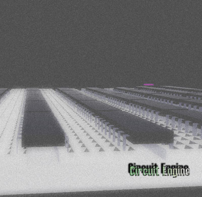
After coding the chip full-adder, we can run the Circuit Engine by giving the CESL file name as the parameter (or you can double click the CESL file if the CESL files in your system have an association with CEngine.exe). The first screen from the Circuit Engine environment is shown in Figure 4.2 (1).
FIGURE 4.2 (1) – Initial Circuit Engine Screen of FullAdder.cesl
As you can see from the figure the breadboard is 20 rows, 5 columns and 5 holes in each node as defined in the code. Chips emerge at the upper left corner of the breadboard in hover mode. The green arrow at the lower left corner of the chip is the Circuit Element Marker which points to the Selected Circuit Element. And the green cubes under the chip are the Hole Markers those make easy to see the current plugging area of the chip and the GREEN color for every cube means that it is convenient to plug the circuit element to plug into corresponding breadboard holes.
The selected circuit element can be moved by the arrow keys to take the chip to any proper place over the breadboard. After movement, it can be plugged by Enter key (same key does unplugging if the circuit element is in plugged state already). LEDs and CABLEs are added into the circuit by pressing the L and K keys respectively and placing of them is same as explained for the chip. Cables have two legs those can be moved independently from each other. In order to toggle the node selection of the cable the TAB key is used. And, in order to select next/previous circuit element the key ] / [ is used. After inserting cables and LEDs and after plugging all circuit elements into proper places, the circuit may have such a view as shown in Figure 4.2 (2).
FIGURE 4.2 (2) – Circuit After Plugging Operations
The upper legs of the LEDs are their voltage legs and they are connected to the legs of the chip numbered as 5 and 6 in order to visualize the information on the corresponding legs. The red and black bars you see on the upper left of the breadboard are the source bars those provides the voltage and ground connections of the circuit respectively. Observe how the cables are connected in order to diffuse the sources throughout the circuit. As you can understand from the design of the chip the upper LED is connected to the CARRY leg and lower is connected to the SUM leg of the chip in the figure. And as you can see from the left side of the chip the legs BIT1 and BIT2 are supplied with voltage but the BIT3 leg is not (the cable over the BIT3 leg is in hover mode). In this situation, the LED which is connected to the sum leg is off mode and the LED which is connected to the carry leg is on mode which corresponds the binary number 10 (Carry = 1, Sum = 0) which is 2 in decimal. The LEDs those in on mode are responded as a light RED color as upper LED in the figure.
I believe in that this program will give a noteworthy experience to the students who take courses of Logic Design and Computer Architecture I-II. Every student can construct their circuits in their homes without spending money or without worry about gathering the required equipment for their design tests. Also, Circuit Engine can be used in schools those cannot afford a logic lab for educational purpose. Even, it can be used any individual who want to learn Logic Design with the support of a Logic Design Lab in his/her home.
Even The Circuit Engine can complete some basic tasks about the Logic Design Circuits, It is not a project that is exactly completed. I hope that this project can find developers and be improved so that it can be used in schools or some other places for humankind.
References
Salamah, M., 1999, Lecture Notes on Computer Architecture I CMPE-224, Eastern Mediterranean University, T.R.N.C.
Woo M. & Neider J. & Davis T. & Shreiner D., 1999, The Official Guide to Learning OpenGL, Version 1.2 / OpenGL Architecture Review Board, Addison-Wesley, Massachusetts
Mano, M.M. & Kime, C.R., 2000, Logic and Computer Design Fundamentals, Prentice-Hall, New Jersey
6. SCREEN SHOTS
Asyncronous Circuit Example (1)
Asyncronous Circuit Example (2)
Dual 4 Input Mux (1)
Dual 4 Input Mux (2)
Full Adder (1)
Full Adder (2)
Circuit Engine 2. Cover
I've graduated from computer engineering department in 2004 July, and developed the Circuit Engine as my graduation project at Eastern Mediterranean University (EMU). I've also graduated from MBA, Istanbul University in 2008 February. From 2004 until now, I've developed many web sites (B2B, B2C). Currently work for Siemens AG (http://siemens.com/ingenuityforlife) as a R&D Engineer (IoT) and I still continue to develop my personal projects about encryption algorithms, maths, OpenGL, Stock Exchange Market Analyses and Real-time Systems, MultiThreaded Applications and Web Solutions (mostly ASP.NET C#, JQuery/JS, MVC, WinForms, Win/Web Services, T-SQL and less PHP, ASP, MySQL and some possible other methods about problem solving if necessary). Also personal profession of photography : https://www.instagram.com/egldgn/
Circuit Engine base URL : https://sites.google.com/view/circuitengine


 General
  News
News  Suggestion
  Question
  Bug
Bug  Answer
  Joke
Joke  Praise
  Rant
Rant  Admin
Admin 


 )
)