Introduction
This is a custom control built using VB.NET. This control is designed to allow users to implement any number of phases of a process and to see how far they have to go, what "phase" they are currently in, and to optionally indicate when the user is ready to move to the next "phase".
Background
I've been working on a personal project for requirements management, and have been looking into a lot of different ways of providing user friendly and visually pleasing ways for users to work with something so complex as software requirements and project management of those requirements. One of my screens is a summary of a requirement and its current "phase". I wanted to have something that uses color and is fully interactive. I don't like the standard rectangular look and feel of most applications because, to me, it doesn't indicate direction. I've also come across something similar in shape, only to find they are using rectangles overlapping the polygon shapes. Those resulted in being able to click in one polygon (such as the tails) and it would assume you meant the other polygon. I also wanted to do some research on custom controls. What better way to do that but by creating one.
Using the Code
The code is broken into three main areas:
ddPhaseProgressBarItem - The class holding the information for each individual polygon.dmPhaseProgressBar - The custom control which is the container for the collection of ddPhaseProgressBarItem classes. It handles the organization, look, and feel of each polygon item. It determines the selected index of the collection of "phases".- Demo form - This is used to implement the custom control and add a custom list of "phases". This is an interactive set up to allow for users to examine the features of the control.
Step 1: The Polygon Item
The class ddPhaseProgressBarItem contains all the information needed to fully draw the polygons. The Polygons attribute is an array of points used to draw two shapes, FillPolygon and DrawPolygon. You have to execute the Fill before the Draw method to ensure that the border will be visible to the user.
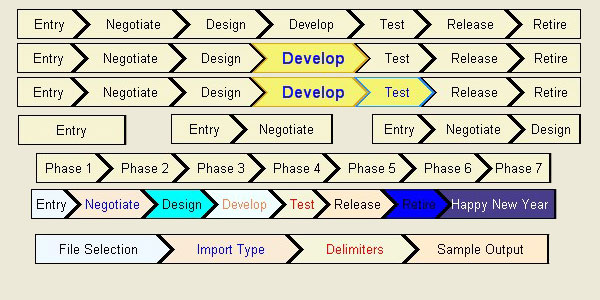
There are four basic shapes that are implemented in this control.
Note: Use the fourth row off the title graphic to see all three shape sets.
Shape Set 1: One Phase Item
This shape will be used when there is only one tab for the progress bar. It would be very counterintuitive since this is a progress bar. However, there could be times when this is a requirement.
This polygon shape is a simple rectangle.
Shape Set 2: Two Phase Items
This shape set has the two special case shapes that are used from here on out. The left shape is a five point polygon. The right shape is also a five point polygon.
The first polygon will be a simple rectangle with the right side coming to a point half way down and outward from the rectangle.
The second polygon will be a simple rectangle with the left side coming to a point half way down and inward to the rectangle.
Shape Set 3: Three or More Phase Items
This shape set will be used when there are three or more tabs. The middle tab will be repeated until all phases are defined.
The first and last polygons are the same as Shape Set #2.
The middle polygon is a simple rectangle with the left side coming to a point half way down and inward to the rectangle, and the right side coming to a point half way down and outward from the rectangle.
Step 2: The Custom Control
The custom control is where the collection of the ddPhaseProgressBarItems is held and the overall shapes are determined. Now that the shape sets are defined, we can use those definitions to determine which shape set to follow, then report the state of each polygon. We will also keep the additional state to allow for "blinking", by having a timer control added, so that users could be notified that the next "phase" is ready. Example: When doing the Import Text from MS Excel, you have four main steps that could be represented here. See the bottom bar in the title graphic.
As you may have already guessed, since this is a control, most of the work is done at the OnPaint method. And you'd be right. These steps are done at the initialization of the control, and steps 2 - 5 repeated for the OnPaint event:
- Set the values for each polygon (
Text, BorderColor, BackgroundColor, etc.). - Determine the extra space in the control to be shared amongst the polygons.
- Determine the shape of each polygon.
- Draw each polygon to the screen.
- Draw text to the polygon.
Step 2.1: Setting the Values for Each Polygon
This step is to set all the values that you want to change from the defaults and to add the text for each polygon that you are adding to the control. I've preset some values so that developers can see the control in action at design time, so you'll have to clear those first with a clearPolygons method. At that point, you generate a new polygon item object, ddPhaseProgressBarItem, setting all the values you want, until you are done adding all your items.
This sample shows all the attributes being set with random values:
Me.SuspendLayout()
Dim PhaseProgressBarItem As New ddPhaseProgressBar.PhaseProgressBarItem
PhaseProgressBarItem.Text = "File Selection"
PhaseProgressBarItem.Font = New Font("Arial", 10, FontStyle.Regular)
PhaseProgressBarItem.Font_Selected = New Font("Arial", 12, FontStyle.Bold)
PhaseProgressBarItem.FontColor = Color.FromArgb(&HFF000000)
PhaseProgressBarItem.FontColor_Selected = Color.FromArgb(&HFF0000FF)
PhaseProgressBarItem.BackColor = Color.FromArgb(&H78FFFFCC)
PhaseProgressBarItem.BackColor_Selected = Color.FromArgb(&H78FFFF00)
PhaseProgressBarItem.BorderColor = Color.Black
PhaseProgressBarItem.BorderColor_Selected = Color.BlueViolet
PhaseProgressBar1.AddPhase(PhaseProgressBarItem)

PhaseProgressBarItem = New ddPhaseProgressBar.PhaseProgressBarItem
PhaseProgressBarItem.Text = "Import Type"
PhaseProgressBarItem.Font = New Font("Arial", 10, FontStyle.Regular)
PhaseProgressBarItem.Font_Selected = New Font("Arial", 12, FontStyle.Bold)
PhaseProgressBarItem.FontColor = Color.FromArgb(&HFF000000)
PhaseProgressBarItem.FontColor_Selected = Color.FromArgb(&HFF0000FF)
PhaseProgressBarItem.BackColor = Color.FromArgb(&H78FFFFCC)
PhaseProgressBarItem.BackColor_Selected = Color.FromArgb(&H78FFFF00)
PhaseProgressBarItem.BorderColor = Color.Black
PhaseProgressBarItem.BorderColor_Selected = Color.Blue
PhaseProgressBar1.AddPhase(PhaseProgressBarItem)

PhaseProgressBarItem = New ddPhaseProgressBar.PhaseProgressBarItem
PhaseProgressBarItem.Text = "Delimiters"
PhaseProgressBarItem.Font = New Font("Arial", 10, FontStyle.Regular)
PhaseProgressBarItem.Font_Selected = New Font("Arial", 12, FontStyle.Bold)
PhaseProgressBarItem.FontColor = Color.FromArgb(&HFF000000)
PhaseProgressBarItem.FontColor_Selected = Color.FromArgb(&HFF0000FF)
PhaseProgressBarItem.BackColor = Color.FromArgb(&H78FFFFCC)
PhaseProgressBarItem.BackColor_Selected = Color.FromArgb(&H78FFFF00)
PhaseProgressBarItem.BorderColor = Color.Black
PhaseProgressBarItem.BorderColor_Selected = Color.DodgerBlue
PhaseProgressBar1.AddPhase(PhaseProgressBarItem)

PhaseProgressBarItem = New ddPhaseProgressBar.PhaseProgressBarItem
PhaseProgressBarItem.Text = "Sample Output"
PhaseProgressBarItem.Font = New Font("Arial", 10, FontStyle.Regular)
PhaseProgressBarItem.Font_Selected = New Font("Arial", 12, FontStyle.Bold)
PhaseProgressBarItem.FontColor = Color.FromArgb(&HFF000000)
PhaseProgressBarItem.FontColor_Selected = Color.FromArgb(&HFF0000FF)
PhaseProgressBarItem.BackColor = Color.FromArgb(&H78FFFFCC)
PhaseProgressBarItem.BackColor_Selected = Color.FromArgb(&H78FFFF00)
PhaseProgressBarItem.BorderColor = Color.Black
PhaseProgressBarItem.BorderColor_Selected = Color.IndianRed
PhaseProgressBar1.AddPhase(PhaseProgressBarItem)

Me.ResumeLayout()
I used the SuspendLayout and ResumeLayout for speed, as I want to minimize the blinking of the control being redrawn.
Step 2.2: Filling in the Extra Space
This step is to determine the control's length and then the total base length of the polygons so that we can determine the extra space that needs to be evenly distributed to all the polygons to fill in the control's overall length. That way, the user/programmer could resize the control, and not change the overall visible space or have to modify the text spacer values to get the text centered properly.
We do this by measuring each polygon's text plus the preset text buffer value, adding them together for what I'm calling the overall base length. That value subtracted from the control's width will give us the "space" that needs to be filled by our secondary text buffer value. Divide that result by the number of polygons, and you have your new secondary text buffer value.
Using the .NET function MeasureString(string to be measured, font to be used), we get a two dimensional object that gives us the overall height and width of the text we are measuring. Since this version of the control (hey, I can't do everything for you :D) is only concerned with the width, that's what we are going to work around. Because of the shape sets that I chose, we only have to deal with the width of the text plus the text buffer value; the points coming into and out of the rectangles actually compliment each other, and the last polygon doesn't point out, so we don't have to account for them in the measurements.
Here's the code function that determines the secondary text buffer (TextBufferForCentering):
Private Function DetermineTextCenterBuffer(ByVal g As Graphics) As Boolean
Dim returnValue As Boolean = True
Dim overallLength As Single = Me.Width
Dim phasesLength As Single = 0
Dim sFThis As SizeF
For i As Integer = 1 To m_Phases.Count
sFThis = g.MeasureString(m_Phases.Item(i).Text, m_Phases.Item(i).CurrentFont)
If i = 1 And m_Phases.Count = i Then
phasesLength += sFThis.Width + Me.TextBuffer + 2
ElseIf i = m_Phases.Count Then
phasesLength += sFThis.Width + Me.TextBuffer + Me.PointLength + 2
ElseIf i = 1 Then
phasesLength += sFThis.Width + Me.TextBuffer + 2
Else
phasesLength += sFThis.Width + Me.TextBuffer + Me.PointLength + 2
End If
Next
Me.TextBufferForCentering = (overallLength - phasesLength) / m_Phases.Count
DetermineTextCenterBuffer = returnValue
End Function
Step 2.3: Determining the Shapes of Each Polygon
This step is to determine the shape of each polygon as we get to the final drawing phase of this control. Using the previously defined shape sets (see above), we can now draw the shapes using a few pieces of information.
- Width of the text
- Text buffer
- Secondary text buffer (
TextBufferForCentering value) - Control's height
- Point Length (the distance the points of the polygons go outside the rectangle)
Each polygon has a starting point that we first have to determine. That is done using the same method, but adding in the TextBufferForCentering value, as we did for determining the overall length of the polygons together. But, this time, we only count the previous polygons up to the polygon we are currently working on. For example, when we are determining the starting point of the third polygon, we would determine the overall length of the first two polygons, putting the starting point at the end of the second polygon's rightmost point. Remember, we aren't using the point that comes out of the rectangles, because they are complimentary. We will only use the Point Length when determining the actual points, not the starting points. Yes, that is confusing, but that's why sometimes it's easier to explain in code. The DeterminePhasePoly function is where this effort is completed.
For this section, we'll assume that we are working on drawing the third polygon of a greater than three polygon solution.
As you can see in this code snippet, we are determining the starting point of the polygon based on the previous polygon's lengths.
Dim startPoint As Single = 0
...
For i As Integer = 2 To ItemPosition
iPrevious = i - 1
sF = g.MeasureString(m_Phases.Item(iPrevious).Text, _
m_Phases.Item(iPrevious).CurrentFont)
If iPrevious = 1 Then
startPoint += sF.Width + Me.TextBuffer + _
Me.TextBufferForCentering + 2
Else
startPoint += sF.Width + Me.TextBuffer + _
Me.TextBufferForCentering + Me.PointLength + 2
End If
Next i
Now that we have the starting point, we can mathematically determine the rest of the points. We will be drawing this in a clockwise manner (x and y coordinates) so the points are determined like this from the starting point (this is our most complex poly):
- Point 1: x = Starting Point, Y = 0
- Point 2: x = Starting Point + Text Width + Text Buffer + TextCenteringBuffer + Point Length , y = 0
- Point 3: x = Point 2 + Point Length, y = 1/2 Control Height
- Point 4: x = Same as Point 2, but y = Control Height
- Point 5: x = Starting Point, y = Control Height
- Point 6: x = Starting Point + Point Length , y = 1/2 Control Height
With all the poly points determined, we now assign those values to the poly's object values.
m_Phases.Item(i).PolyPoints = DeterminePhasePoly(g, i)
Step 2.4: Drawing the Polygons
The final step is to actually draw the polygons and place the text. Hurrah!
We pull out all the attributes for the polygon we are going to draw. I selected to draw the polygons from right to left, because of overlapping of polygons. When drawing, the last thing drawn is the topmost item. Therefore, if you want to have the appearance of the items "stacking" on top of each other, you must draw the bottommost item first, then work your way to the topmost item. You have to do the same thing when drawing each polygon, too.
penColor = m_Phases.Item(i).CurrentBorderColor
pPen = New Pen(penColor, 2)
bFontBrush = New SolidBrush(m_Phases.Item(i).CurrentFontColor)
bBrush = New SolidBrush(m_Phases.Item(i).CurrentBackColor)
fFont = m_Phases.Item(i).CurrentFont
sText = m_Phases.Item(i).Text
When drawing the individual polygon, we must draw in order:
- background fill
- border
- text
One point of interest you'll probably note when reading the code is that I modified the ddPhaseProgressBarItem to return the colors and text based on the "Selected" state of the polygon, CurrentBorderColor, CurrentFontColor, CurrentFont, and CurrentBackColor. This allows me to simplify the code to draw, because I only ask for current values and not have to test if the polygon is "selected" or not at the drawing phase. I let the object itself determine what color and text it wants presented.
g.FillPolygon(bBrush, m_Phases.Item(i).PolyPoints)
g.DrawPolygon(pPen, m_Phases.Item(i).PolyPoints)
Step 2.5: Placing the Text
Placing the text is the last action needed to complete the drawing portion of the control. But, we need to center it properly, not just drop it any place and expect it to handle it eloquently.
Again, we have to know the shape we are dealing with to properly determine its center point for the text. You may notice we are actually finding the leftmost point for the text to start, not the center of the polygon.
If i = m_Phases.Count And i = 1 Then
xForText = m_Phases.Item(i).polypoints(0).X + _
(Me.TextBuffer / 2) + (Me.TextBufferForCentering / 2)
yForText = (Me.Height - fFont.Height) / 2
ElseIf i = m_Phases.Count Then
xForText = m_Phases.Item(i).polypoints(0).X + _
(Me.TextBuffer / 2) + (Me.TextBufferForCentering / 2) + _
Me.PointLength
yForText = (Me.Height - fFont.Height) / 2
ElseIf i = 1 Then
xForText = m_Phases.Item(i).polypoints(0).X + (Me.TextBuffer / 2) _
+ (Me.TextBufferForCentering / 2) + (Me.PointLength / 3)
yForText = (Me.Height - fFont.Height) / 2
Else
xForText = m_Phases.Item(i).polypoints(0).X + (Me.TextBuffer / 2) + _
(Me.TextBufferForCentering / 2) + Me.PointLength + _
(Me.PointLength / 3)
yForText = (Me.Height - fFont.Height) / 2
End If
Now, draw the text in its proper location:
g.DrawString(sText, fFont, bFontBrush, xForText, yForText)
We're done! The control is now drawn to the screen.
Demo Project
I created a demo project that would allow you, as the reader/developer, to get a good feel of this control. I put the control onto the form using all the features of the control, plus I added in a blinking feature that I didn't go over in this article. That is something I added after outlining, and felt it would be a good thing to research on your own while watching how I built the control. It's not really a required feature to be used.
After loading the project and running it without change to the source code, you should see the control matching the top row phase progress bar from the title image (see above). By clicking on one polygon, it should change to the selected colors and font and set the blinking state of the polygon to its right. Unless, of course, you're at the final phase, then no polygon is set to blink.
Which Polygon Did the User Click on?
After running the demo, it may seem that I missed a very important piece of this code. How do you know which polygon was clicked so I can handle the OnClick event? Well, I intentionally skipped over that because I didn't write that portion. I found a great resource for determining if a point is inside a polygon, by Darel Rex Finley, located here. Even though I had to convert it from C++ to VB.NET, it is still his research that made a very complex procedure simple. Read his article to fully understand it. At the time of writing this article, it handled very complex polygons, and even dealt with voids created by polygons that had crossing points.
Points of Interest
Not having done much graphical based controls before, I found it interesting about having to really watch the order in which I drew items. Basically, from back to front. It also pointed me in the direction of using a new attribute called PenWidth (not in this sample code) to have all the polygons actually touching each other rather than overlapping. You'll notice a +2 in a lot of my computations for drawing and points placement. That's the pen width being accounted for.
The placement of text was a good challenge because I ended up changing how I drew the polygons because of how the text might fall into the points of the tabs which could cause overlapping text and lines. I certainly didn't want that. So, I added more space evenly into the basic shape, but still offset the text to push a little into the points of the polygons.
One thing that annoys me about some controls I've seen, both web and application, is that when they have complex shapes to please the eye, they don't have the actual shape covered for Click events. For example, I've seen tabs shaped similar to mine that when clicking in the point of the polygon, it would either not register the click, or register it to the wrong polygon. That was because the mapped area for the click was actually a rectangle and not the same polygon shape. I know it's easier to do rectangles, but if you've taken the time to generate a polygon for the user to see, you should use the same polygon for the click events.
Debugging this one was kind of annoying as well, because of the graphical nature of the control. I had a bug in it that actually had a problem with drawing the last tab in a two+ tab environment. I was putting the last tab point at the top left of the control instead of at the end of the last tab (poor copy/paste on my part), and because it was drawn first (remember, I draw from right to left), it was below all my other tabs. The problem was when I was testing for the mouse click using Darel's method, I was testing from left to right. I didn't have a "if true, break out" line, so it was getting a "yes, it's in this polygon" value for more than one polygon: the one I was clicking on and the poorly shaped polygon below it. Commenting out the drawing phase of all the polygons I didn't want, and only showing the one I wanted, showed the problem, but I think adding in an opacity value to this control will be a good thing in the future.
Bugs
Currently, I'm only seeing one thing that might be considered a bug in the control.
The control isn't fully handling the "extra space" that is the difference between the polygon's length versus the control's length. There are times when the control isn't filling in all the space. I know it's from the math being done having value after the decimal place that adds up, resulting in a couple of pixels worth of space being seen at the end of the control on the right. I'm working on accounting for that additional space, and will most likely add it to the final polygon.
Ideas for This Control
Since we're on the topic of new stuff, here're a few ideas I've thought of that might be fun to add to this control to make it more useable.
React to minimum heights and widths. By adding in the attributes for minimum height and widths for the entire control, we could better handle form resizing, and raise events to prevent a control from getting too small vertically or horizontally. We could base that on the longest the control could possibly get because of the combinations of font (size and family) and the actual text. In order for this to work, we would either have to restrict functionality, or account for a multitude of possible scenarios. The one that comes up to my mind is to restrict the number of polygons that could be different from the base font. When a polygon is "selected", the font may change, resulting in an increase in height and width for the text. This is accounted for when drawing the control, but on a case by case basis. The overall length of the control changes, which is why I had to add in the secondary spacer for centering text. If we don't restrict the control, things like "if poly1 and poly2 are selected, then the minimum length would be X" scenarios would have to each be run, then the worst case length determined. A simple answer could be just doing all the possible combinations of selected versus unselected and determining the highest number, and you're done. But, would that be right? Not really, but pretty close for government work.
Better coloring. I read a couple of articles here, and saw a tab control that does some mathematical computations for coloring the tabs to give it that glossy or glass reflection look and feel. I don't like just pulling from the standard RGB values either, but that's where this control is starting. Putting better looking colors conforms to the user's need to be shown pretty along with functional. Pretty sells better than functional, just look at Windows vs. Linux :D.
Add Visual Studio design-time control functionality. Beyond the simple attributes, like text spacing values, I would like to see a developer be able to add the phases at design time. Like the DataGridView control. You can add columns to the collection, which would be nice here so you can add the phases, colors, text, etc., without having do it at run time. I can see this control being used statically for things like showing the steps of an import wizard and things of that nature, that won't necessarily need to be dynamically adding/removing phases at runtime.
Globally setting values. I think that some users would benefit from having a global set of values to use for this control. If a user could simply set the global values like background color, selected background color, and border color without having to set it for each polygon, it would speed up coding the control from the beginning. While my demo code shows that you can set all of those items independent of each other, I can certainly see times when a single background color with a matching "selected" background colors, fonts, and all would be set to a single standard for the entire control.
History
- March 2007 - First publish.
Copyright © 2007 Dan Morris. All rights reserved. Do not publish to other sites without my express permission. Link to this article in accordance with this site's policies and procedures.
I started coding when the Indus GT 5 1/4 drive and the Atari 800 were around. So, it's been a while. I enjoy developing the architecture of complex software and doing the project management nowadays.
I still develop for myself and others as I enjoy the constant changing environment and the challenge of learning new things every day.


 General
  News
News  Suggestion
  Question
  Bug
Bug  Answer
  Joke
Joke  Praise
  Rant
Rant  Admin
Admin 


