
Getting Started with Raspberry Pi - Part II - GPIO
3.48/5 (14 votes)
In this article, we would be discussing about the Raspberry Pi - GPIO (General Purpose Input Output) Pins
Note: Request you to please vote and provide comments.
Introduction
In my previous article - Getting Started with Raspberry Pi , we talked about GPIO (General Purpose Input Output). In this article, we will discuss more about the GPIO pins, function of each pin on the Pi board and GPIO numbering.
Getting Started
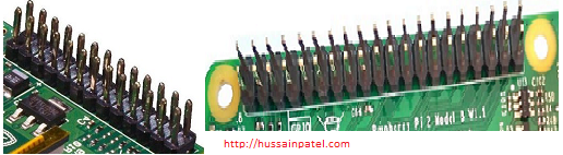
The main difference between a Raspberry Pi (tiny computer) and other computers is the GPIO (General Purpose Input Output) pins (see Figure 1).

Desktop computers are UBIQUITIOUS, i.e., they have a standard input and output (files, keyboard, mouse, touch, print, screen, etc.) and they take information from fixed input, process it and give the results back to the standard output. This means a normal computer / machine does not have an interface to connect with electronic devices like sensor and actuators, this is where the Raspberry pi (tiny computers) GPIO pins play an important role and make Raspberry Pi different from other computers.
The Pi has GPIO pins that stick out from the top of the board. These pins act as an interface between the Raspberry pi and the physical world. These pins are used to communicate (both input / output) with other circuitry such as sensors, actuators, extension boards and custom circuits.
Understanding the Pins
As seen in Figure 2 above, the GPIO pins vary based on the Raspberry Pi model. The previous models have 26 pins and latest models - Raspberry Pi 2 Model B and Raspberry Pi 3 Model B both have 40 Pins.
To maintain backward compatibility, the first 26 pins from previous models still have the same functionality in the new Raspberry pi models (See Figure 3).

As seen in Figure 4, each pin on the Raspberry pi has a function to do and also an alternate function assigned. You can consider these pins like switches which have a function / Alternate function to do and which can be turned on or off. Apart from the regular function / standard I/O pins (GPIO), the alternate functions these pins have are GND (ground), SPI (Serial Peripheral Interface Bus), I2C (inter integrated circuits), power pins and UART (Universal asynchronous receiver /transmitter) pins.
GPIO Numbering
As seen in Figure 4 above the GPIO pins diagram it seems to be pretty complex and confusing and there is no easy way to remember each of the pins, you need to keep a printed reference sheet on top when using them.

There is a solution to this problem and in the Raspberry Pi world, there are two different numbering schemes used when referencing Pins.
- Using the BCM – Broadcom chip-specific pin number – example GPIO10, GPIO23, GPIO24, etc.
- Physical numbering – where each number is based on the physical position of the pin. (Hold the Raspberry Pi up facing you vertically with the pins on the right side, then start counting from top left as pin 1 and next pin as 2 on the first row and the pin below 1 as 3 and below 2 as 4 and so on).


Note: You are free to use any of the above GPIO numbering systems, but while invoking the GPIO pins in programs (like Python or C#), your code should reference one of the numbering systems you are going to use.
Example in a Python program – code looks like this:
import RPi.GPIO as GPIO
GPIO.setmode(GPIO.BCM)
GPIO.setup(18,GPIO.OUT)
GPIO.BOARD – is the physical numbering system and GPIO.BCM is the Broadcom number system.
In the next article, we will talk about the difference in each of the Raspberry Pi models and the pros and cons.
Don’t worry if you don’t understand the above code. We will learn all about it in future articles.
Important Warning: You have to be careful when connecting devices, the GPIO pins directly with wires (called jumper cables)- if these wires are connected to wrong pins, it might damage the Pi board, so please read the instructions carefully before connecting wires directly to the pins.
I would highly recommend using a Breadboard – where you can create the dummy circuits on the breadboard and then connect only to the required pins on the Pi. I would also recommend using a “breakout circuit” to connect the Raspberry Pi with breadboard. One end breakout board is connected to the Raspberry Pi and the other end into the breadboard.
This article was published on my website – hussainpatel.
References
In the next article, we would talk about Breadboard and make our first circuit.
Hope this helps. Please leave your comments and feedback.
Happy learning! Happy making!