Introduction
SomaCubeWPF is a WPF program that demonstrates 3D graphics techniques. It allows you to manipulate the famous Soma Cube puzzle pieces. The code is similar to my Orbital Mechanics WPF program. If you are not familiar with WPF and 3D graphics, you might want to look at the section "3D Graphics and WPF" in that project. One difference between the two projects is SomaCubeWPF uses two viewports and two cameras, described below. Having two cameras allows you to view the Soma Cube pieces from different perspectives, making it easier to manipulate the pieces.
Background
The Soma Cube is a puzzle consisting of seven pieces. Six of the pieces are made up of 4 small cubes (the six pieces are called "tetra-cubes" because tetra is the Greek word for four), and one is made up of 3 small cubes (the piece is a "tri-cube"), for a total of 27 small cubes. The seven pieces can be arranged into a single larger cube, or placed in an infinite number of arrangements. The image above shows the seven pieces arranged in what is called the "dog" by Soma enthusiasts. Just to assemble the seven pieces into a larger cube, there are more than 200 solutions! I've included the larger cube and the "dog" solutions as settings files cube.txt and dog.txt in the SettingsFiles directory. Settings files are discussed below.
Before we dive into the code, let's get familiar with the seven pieces. Though the nomenclature may seem a little unwieldy at first, it will become very familiar with a little practice. I'm following the naming convention used here where each piece has a name and a number:
- L Tri Cube, #1

- L Tetra Cube, #2
- T Tetra Cube, #3
- S Tetra Cube, #4
- Left Screw Tetra Cube, #5
- Right Screw Tetra Cube, #6
- Branch Tetra Cube, #7
Each face of each of the small cubes that comprise a piece is labeled with a face label. For example, Piece Number 3, the "T Tetra Cube", has 18 faces indicated by the lower-case letters a through r. So the T Tetra Cube's faces are 3a, 3b, 3c, and so on up to 3r. These face labels are helpful in maintaining the orientation of a piece when you are translating or rotating it. The face labels can be toggled on and off using the L key or by using the View menu.
Each of the small cubes that comprise a piece also has a label; the cube label is the piece number and an upper-case letter. So the S Tetra Cube - being made of 4 small cubes - has cube labels 4A, 4B, 4C, and 4D, as shown above. The cube labels are used to indicate when the pieces intersect with each other. The cube labels can be toggled on and off using the C key or by using the View menu. You can have both the face labels and cube labels displayed simultaneously, but in general, it is less confusing to have only one or the other displayed. In these images, the T Tetra Cube and Right Screw Tetra cube's face labels are shown; for the other pieces, the cube labels are shown.
Using the Code
Download and extract the project, and open SomaCubeWPF.sln with Visual Studio. It consists of a single project. Before running the program, you will first need to set the location of the image files on your machine in app.config, for example:
<setting name="ImageFileLocation" serializeAs="String">
	<value>C:\MyProjects\SomaCubeWPF\Images\</value>
</setting>
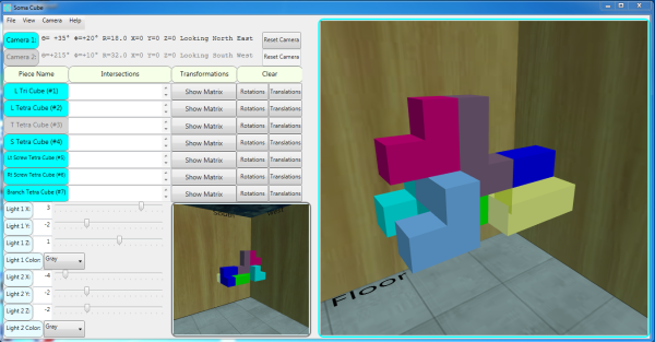
After modifying and saving app.config, build the solution using "Build->Rebuild Solution" from the Visual Studio Main Menu. Use Ctrl-F5 to Start without Debugging and display a WPF Form as shown in the image above. The WPF Form has the main (larger) viewport on the right-hand side. The left-hand side is comprised of, starting at the top and moving downward:
- The Menu bar
- The camera settings for both cameras
- A line for each of the seven pieces. Each line for a piece shows whether or not it is selected, and whether or not it intersects (or collides) with another piece. You can also display the translation matrix by clicking the "Show Matrix" button, and clear the piece's rotations and/or translations using the "Rotations" and "Translations" button under the "Clear" label.
- The "Flashlight" controls
- The secondary (smaller) viewport
Selecting and Moving the Soma Cube Pieces
Selection
In order to move a piece, you must first select it. The selected piece will be shown in its selected color, while all other pieces will be shown in their not-selected color. (See Configuring Colors for information on how to set the selected and not-selected colors.) On the left-hand side of the form, the name of the selected piece (or pieces) will have a cyan background, and the names of non-selected pieces will have a gray background. You can select a piece in one of three ways:
- Use the Spacebar to select the next piece. For example, if piece 5 is currently selected, pressing the space bar will un-select piece 5 and select piece 6. Shift-Spacebar will un-select the current piece and select the previous piece.
- Type the piece (1-7) number using the numeric keypad.
- You can left-click on a piece in the main viewport with the mouse.
You can also select multiple pieces by holding the Ctrl key when using techniques 2 and 3. For example, if no pieces are currently selected, to select pieces 1, 3, and 6, press 1 on the numeric keypad, then press Ctrl-3 and Ctrl-6. If a piece is currently selected, pressing the Ctrl key and the selected piece number will un-select the piece. If you select multiple pieces, you can move them as a single unit using the translation keys.
Rotation
The keys for rotation of the selected piece are:
- Use X, Y, Z to rotate a single selected piece about its X, Y and Z axes, respectively, by 90 degrees. (The 90 degrees is specified in the app.config file as
SomaPieceRotateIncrement described below in Miscellaneous Parameters.) Only a single piece can be rotated; if you try to rotate multiply selected pieces, a dialog box will be displayed with the message: "Rotating multiple pieces not allowed (select exactly one piece)". If zero pieces are selected and you use X, Y, Z, a dialog box will be displayed with the message: "You must select at least one piece to rotate or translate (no pieces currently selected)". You will also get this message if use any of the 6 translation keys (described below) when zero pieces are selected. - Shift X, Y, Z will rotate the selected piece about its negative X, Y and Z axes, direction by 90 degrees.
The rotations are animated using WPF's Rotation3DAnimation class giving what I believe to be a very cool effect. The animation speed can be set via the Miscellaneous Parameters. You may want to use a higher or lower value than the default animation speed depending on the speed of your machine. Setting the animation speed to zero will disable the animation.
Translation
It is helpful to think of the 7 pieces in a world in which you can move the selected piece in any of the four compass directions as well as up and down. Thus, there are 6 translation keys for translating the selected piece. Using these six directions, moving a piece south, up, or west corresponds to movement along the global +X, +Y, +Z axes, respectively. Similarly, moving the piece north, down or east corresponds to movement along the global -X, -Y, -Z axes, respectively. There are two translations, a coarse and a fine translation. These are specified by in the Miscellaneous Parameters as SomaPieceTranslateIncrementCoarse and SomaPieceTranslateIncrementFine, respectively.
- To translate the selected piece in World coordinates using coarse translation, use the N, S, E, W, U, and D keys. These are short for North, South, East, West, Up and Down. The default
SomaPieceTranslateIncrementCoarse is 4.0, so pressing the S key 2 times will translate the selected piece (or pieces) 8 units in the +X direction (South). - Use Shift and one of the 6 translation keys to translate the selected piece in the opposite direction. For example, pressing Shift-W will move the piece East.
- To translate the selected piece by the fine translation, use Ctrl and one of the 6 translation keys. The default
SomaPieceTranslateIncrementFine is 0.5, so pressing the Ctrl-U key 3 times will translate the selected piece 1.5 units up, that is, in the +Z direction. - If multiple pieces have been selected, they will all be translated by the same amount. This is handy if you have a group of pieces you want to move as a single unit.
The translations are animated using WPF's DoubleAnimation class. As with the piece rotation animation, the animation speed can be set via the Miscellaneous Parameters. Setting animation speed to zero will disable the animation.
For an example of setting SomaPieceRotateIncrement, SomaPieceTranslateIncrementCoarse, and SomaPieceTranslateIncrementFine in app.config, see Miscellaneous Parameters.
Undo and Clear
- Each piece has a list of Transformation Matrices. As you rotate and translate a piece, the current Transformation Matrix is added to the end of the piece's list. Pressing Ctrl-Z will undo the last movement (rotation or translation) by removing the last item in the list, and then using the last Transformation Matrix in the updated list as the current Transformation Matrix. See
#region undo in SomaPiece.cs for details. - To clear all the rotations for a given piece, click the "Clear Rotations" button. To clear all the translations, click the "Clear Translations" button. These actions will not clear the list of rotations and translations, so pressing Ctrl-Z will still undo the last movement.
Practice
With a little practice, you will find that you can move the selected piece with ease and precision. In the 4 images below, I used the keyboard to orient the selected piece (the Left Screw Tetra Cube) using the following steps:
- Open the settings file (described below) practice.txt in the SettingsFiles directory using "File->Open..." from the menu bar. Note that the Left Screw Tetra Cube (piece #5) is the only selected piece.
- Rotate the Left Screw Tetra Cube (piece #5) about its X axis 90° by pressing the X key once.
- Translate it along its -X axis (North) 2 units by pressing the N key once.
- Translate it along its -Z axis (East) 2 units by pressing the E key once.
Note that you can press CTRL-Z 3 times to undo these 3 moves.
The menu bar has four items: File, View, Camera, and Help.
File
Under "File", there are four options:
- "Open...": allows you to open a previously saved settings file. Opening a settings file will clear all of your previous rotations and translations! The image above shows the results of opening the settings file dog.txt in the SettingsFiles directory.
- "Save As...": allows you to save your settings to a text file. You can save the settings file to any directory you wish.
- "Reset": sets the pieces to the settings in
Properties.Settings.Default. This action will clear all of your previous rotations and translations! You can also use the Esc key to reset. - "Exit": Exits the program.
View
Using "View" on the menu bar, you can control the drawing of the:
- X, Y, Z Axes of the selected piece (or pieces if multiple pieces have been selected.) These are the axes about which the X, Y, and Z rotations take place.
- Background, a box with textures applied showing the north, east, south and west compass directions, as well as up and down.
- Cube labels, used to show intersections.
- Face Labels on the pieces, used to help orient the pieces.
- Global X, Y and Z axes (centered at the origin).
- "Flashlights", showing the directional lights. The code for both the background and flashlights is taken from my Clipping Plane in WPF 3D project.
- Randomize to arrange the pieces randomly. Note that even if you randomize the pieces, you can still use CTRL-Z to undo the piece's random moves.
Camera
In order to make it easier to see all the pieces, SomaCubeWPF has two viewports and thus two cameras, one of which is active at any time. The active viewport is indicated by a cyan border around the active viewport, and a cyan label for the active camera, either "Camera 1" or "Camera 2" in the upper left-hand side of the form.
Using "Camera" on the menu bar, you can:
- Select the active Camera, either Camera 1 or Camera 2.
- Open the Camera Settings Dialog to set the active camera's position using six Camera settings (tilt (Φ), rotation (ϴ), zoom distance (R), X, Y, and Z).
- Move the camera to point along the positive or negative X, Y or Z axes. (Look South, Up, West, North, East, Down, respectively.) You can also use two consecutive keystrokes to accomplish this: QS, QU, QW, QN, QE, and QD. These are short for "Quick South", "Quick Up", "Quick West", "Quick North", "Quick East", and "Quick Down".
The active camera can be moved by using the left, right, up, down, plus and minus keys:
- Up/Down Arrow: tilt camera by phi (Φ) degrees
- Right/Left Arrow: rotate camera by theta (ϴ) degrees
- Plus/Minus: zoom camera In/Out by R units
You can also pan the camera:
- Ctrl Left-Arrow: pan camera along -X axis
- Ctrl Right-Arrow: pan camera along +X axis
- Shift Up-Arrow: pan camera along +Y axis
- Shift Down-Arrow: pan camera along -Y axis
- Shift Left-Arrow: pan camera along -Z axis
- Shift Right-Arrow: pan camera along +Z axis
The six Camera settings (phi, theta, R, X, Y, and Z) are displayed on the upper left side of the form. The calculation of the six settings is in the Camera class which uses the Media3D PerspectiveCamera class. You can reset the active camera to the default settings by clicking the active camera's "Reset Camera" button.
Help
"Help" on the menu bar displays a message describing the keystrokes to orient the cameras and move the pieces.
The Soma Piece Class
The SomaPiece class is at the heart of SomaCubeWPF. Here is an excerpt showing some of the main fields.
public class SomaPiece
{
    public Cube3D[] Cubes { get; set; }
    public Matrix3D cumulativeRotationAndTranslation;
    public List<rotationandtranslation> previousRotationAndTranslationList { get; set; }
    public readonly Point3D[] Points;
    protected Model3DGroup ModelGroup { get; set; }
    protected MeshGeometry3D Mesh { get; set; }
    public GeometryModel3D PieceModel { get; set; }
}</rotationandtranslation>
I've strived to use descriptive names for the fields, but in the interest of clarity, here is a list of what these fields are:
- The
Cube3D[] Cubes are used to determine intersections of pieces. - The
Matrix3D cumulativeRotationAndTranslation is the 4x4 Transformation Matrix that describes the state of the piece. It contains all the rotations and translations the piece has undergone. - The
previousRotationAndTranslationList is a list of each rotation and translation that has occurred. It is used when you press CTRL-Z to undo a movement. - Each of the seven pieces have an array of points,
Point3D[] MyPoints. They are copied to the Point3D[] Points array in each of the piece's constructor. The Model3DGroup ModelGroup, MeshGeometry3D Mesh, and public GeometryModel3D PieceModel are used to build the Soma pieces from triangles represented by the Point3D[] Points array as described in "3D Graphics and WPF".
Piece Intersections
In order to determine if pieces intersect (which obviously can only happen with software Soma pieces), I use a very simple scheme: inside every small cube that makes up a piece, there is a slightly smaller cube of type public class Cube3D that is not drawn but has its own array of points, Point3D[] Points. In the GetIntersectingCubes() method, each Cube3D of the selected piece is checked to see if it is inside a Cube3D of another piece. If so, there is an intersection of the two pieces.
For example, on the left-hand side of the side image below, the L Tri Cube (piece #1) and the T Tetra Cube (piece #3) are not intersecting (that is why the Cube3D are "slightly smaller" - if they were the exact same size as the small cube that contains it, the two pieces would be considered to be intersecting by the CubesIntersect() method when in fact they are not intersecting). When I select the L Tri Cube and use CTRL-E to move it 0.5 units East (the image on the right), the CubesIntersect() method (which uses C#'s great LINQ feature) determines that the L Tri Cube's 1B cube intersects with T Tetra Cube's 3D cube. (Note that after I moved the L Tri Cube West, I used multiple select to select both the L Tri Cube and the T Tetra Cube to show the cube labels for clarity.)
In the upper left-hand side of the form (a portion of which is shown below), the messages in the text box under "Intersections" list which pieces the piece intersects with, and the labels of the smaller cubes that intersect. In this example, there is one intersection, so there is only one message. For the L Tri Cube (piece #1), the message is "T Tetra Cube (1B, 3D)". This means the L Tri Cube and T Tetra Cube intersect at the L Tri Cube's 1B small cube, and the T Tetra Cube's 3D small cube, as shown in the image above. Since the pieces can intersect in an almost unlimited number of ways, the Intersections text box is a multi-line text box with vertical scroll bars and one message per line. The objective of moving the Soma pieces is to have zero intersections.
Settings File
You can save your settings to a text file by using "File->Save As..." from the menu bar. The settings saved are:
- Current view (Axes On/Off, Background On/Off, Cube Labels On/Off, Face Labels On/Off, Global Axes On/Off, and Flashlights Visible/Invisible)
- Transformation Matrix for each of the seven pieces, that is, its cumulative rotations and translations
- Which piece or pieces are selected
- Camera settings (CameraTheta, CameraPhi, CameraR, CameraX, CameraY, and CameraZ) for both cameras, as well as the active camera
- Flashlight locations and colors
When you start SomaCubeWPF at a later time, you can restore your settings from that file by using "File->Open..." and specifying the name of the text file. Opening a settings file will clear all of your previous rotations and translations!
Configuration File
There are several settings in app.config you can set to customize SomaCubeWPF. As mentioned previously, before running the program, you must first set the location of the Image files on your machine, for example:
<setting name="ImageFileLocation" serializeAs="String">
	<value>C:\MyProjects\SomaCubeWPF\Images\</value>
</setting>
The settings fall into the following categories:
- View Settings
- Camera Settings
- Piece Transformation Matrix Parameters
- Colors
- Miscellaneous Parameters
Configuration File - View Settings
<setting name="AxesOn" serializeAs="String">
	<value>True</value>
</setting>
<setting name="BackgroundOn" serializeAs="String">
	<value>True</value>
</setting>
<setting name="FaceLabels" serializeAs="String">
	<value>True</value>
</setting>
<setting name="FlashlightsVisible" serializeAs="String">
	<value>False</value>
</setting>
<setting name="GlobalAxesOn" serializeAs="String">
	<value>False</value>
</setting>
Configuration File - Camera
The parameters for the two cameras can be set as shown below:
<setting name="Camera1R" serializeAs="String">
	<value>15</value>
</setting>
<setting name="Camera1Phi" serializeAs="String">
	<value>10</value>
</setting>
<setting name="Camera1Theta" serializeAs="String">
	<value>20</value>
</setting>
<setting name="Camera1X" serializeAs="String">
	<value>1</value>
</setting>
<setting name="Camera1Y" serializeAs="String">
	<value>2</value>
</setting>
<setting name="Camera1Z" serializeAs="String">
	<value>3</value>
</setting>
<setting name="Camera2R" serializeAs="String">
	<value>47</value>
</setting>
<setting name="Camera2Phi" serializeAs="String">
	<value>10</value>
</setting>
<setting name="Camera2Theta" serializeAs="String">
	<value>230</value>
</setting>
<setting name="Camera2X" serializeAs="String">
	<value>9</value>
</setting>
<setting name="Camera2Y" serializeAs="String">
	<value>10</value>
</setting>
<setting name="Camera2Z" serializeAs="String">
	<value>11</value>
</setting>
<setting name="Camera1Selected" serializeAs="String">
	<value>True</value>
</setting>
Configuration File - Piece Transformation Matrix
In my Clipping Plane Part 3 project, I described the 3D Transformation Matrix and how to rotate a model about an axis and translate it along an axis. This project uses the same technique.
The 4x4 Transformation Matrix of each of the pieces can be set as shown below. This is for advanced users only and caution is advised as incorrectly setting these can cause the pieces to be rendered incorrectly!
<setting name="LTriCubeMatrix" serializeAs="String">
	<value>1,0,0,0,0,1,0,0,0,0,1,0,-1.5,1,3,1</value>
</setting>
<setting name="LTetraCubeMatrix" serializeAs="String">
	<value>-1,0,0,0,0,0,-1,0,0,-1,0,0,-0.5,-2,2,1</value>
</setting>
<setting name="TTetraCubeMatrix" serializeAs="String">
	<value>-1,0,0,0,0,0,1,0,0,1,0,0,-0.5,-2,0,1</value>
</setting>
<setting name="STetraCubeMatrix" serializeAs="String">
	<value>0,-1,0,0,-1,0,0,0,0,0,-1,0,-1.5,0,1,1</value>
</setting>
<setting name="LeftScrewTetraCubeMatrix" serializeAs="String">
	<value>0,0,1,0,0,1,0,0,-1,0,0,0,1.5,1,3,1</value>
</setting>
<setting name="RightScrewTetraCubeMatrix" serializeAs="String">
	<value>1,0,0,0,0,1,0,0,0,0,1,0,-2.5,1,-1,1</value>
</setting>
<setting name="BranchTetraCubeMatrix" serializeAs="String">
	<value>-1,0,0,0,0,-1,0,0,0,0,1,0,1.5,1,-1,1</value>
</setting>
Configuration File - Colors
The colors of the pieces when they are selected, as well as the colors when they are not-selected can be set as shown below:
<setting name="LTriCubeColorSelected" serializeAs="String">
	<value>#FFFF0080</value>
</setting>
<setting name="LTetraCubeColorSelected" serializeAs="String">
	<value>#FFFF6684</value>
</setting>
<setting name="TTetraCubeColorSelected" serializeAs="String">
	<value>#FFFFFF00</value>
</setting>
<setting name="STetraCubeColorSelected" serializeAs="String">
	<value>#FF8080FF</value>
</setting>
<setting name="LeftScrewTetraCubeColorSelected" serializeAs="String">
	<value>#FF0000FF</value>
</setting>
<setting name="RightScrewTetraCubeColorSelected" serializeAs="String">
	<value>#FF8CBFFF</value>
</setting>
<setting name="BranchTetraCubeColorSelected" serializeAs="String">
	<value>#FF00FFFF</value>
</setting>
<setting name="BackgroundColor" serializeAs="String">
	<value>#FFDCDCDC</value>
</setting>
<setting name="LTriCubeColorNotSelected" serializeAs="String">
	<value>#88FFC4E8</value>
</setting>
<setting name="LTetraCubeColorNotSelected" serializeAs="String">
	<value>#88FFCCCC</value>
</setting>
<setting name="TTetraCubeColorNotSelected" serializeAs="String">
	<value>#88DDDD00</value>
</setting>
<setting name="STetraCubeColorNotSelected" serializeAs="String">
	<value>#88C0C0FF</value>
</setting>
<setting name="LeftScrewTetraCubeColorNotSelected" serializeAs="String">
	<value>#88EEEEFF</value>
</setting>
<setting name="RightScrewTetraCubeColorNotSelected" serializeAs="String">
	<value>#88ABBFFF</value>
</setting>
<setting name="BranchTetraCubeColorNotSelected" serializeAs="String">
	<value>#88DDFFFF</value>
</setting>
Configuration File - Miscellaneous
Parameters that do not fall into the other categories can be set as shown below:
<setting name="AnimationSpeed" serializeAs="String">
	<value>1.5</value>
</setting>
<setting name="SelectedPieces" serializeAs="String">
	<value>0%1%2%3%4%5%6:1</value>
</setting>
<setting name="SomaPieceTranslateIncrementCoarse" serializeAs="String">
	<value>2</value>
</setting>
<setting name="SomaPieceTranslateIncrementFine" serializeAs="String">
	<value>0.5</value>
</setting>
<setting name="SomaPieceRotateIncrement" serializeAs="String">
	<value>90</value>
</setting>
<setting name="BackgroundColor" serializeAs="String">
	<value>#FFDCDCDC</value>
</setting>
Points of Interest
In a future version, I plan on demonstrating an algorithm to solve the Soma Cube.
History
- 17th February, 2019: Version 1.0


 General
  News
News  Suggestion
  Question
  Bug
Bug  Answer
  Joke
Joke  Praise
  Rant
Rant  Admin
Admin 


