
Family Tree
4.98/5 (18 votes)
The development of a Family Tree application.
Introduction
This is only one example (or a set of preliminary examples showing the way to one real application) from the book World of Movable Objects. The idea of the main example is the development of a Family Tree application through exactly the same ideas and classes as can be used in the design of different block diagrams with different purposes and visual presentation of elements. If you are not interested in a Family Tree application this is the right moment to stop wasting time on this article.
The book together with its huge demo project and several other helpful things can be downloaded from http://sourceforge.net/projects/movegraph/files/?source=directory.
If you are not sure whether you are interested at looking into the development of a Family Tree application or not, you can try looking at the working application. To start the application, its EXE file must be accompanied by MoveGraphLibrary.dll. There is also a short description for users of this program; the text below is for developers.
To get all the code for the files mentioned below, download WorldOfMoveableObjects.zip. This is the whole project which, among many other examples, includes all the needed files.
The text below is only some part from Chapter 20 of the mentioned book. In order not to add any mistakes during renumbering, all figures below have the same numbers as in the original text of the book. It is a bit strange to see the pictures in an article starting from 20.30, but I think it is a minor inconvenience in comparison with the wrong text.
Of straight lines and simple comments only

Closer to the end of this book the examples become more and more complicated. They are not any more the artificial examples to demonstrate one or another new feature but mostly they are the real applications which we use in our everyday work. The main example in this section is also a real application which I use myself. I have a feeling that a lot of other people will like to use it, so I also put this particular application as a stand alone one among other files available at www.SourceForge.net. But before we come to the final program in this section, there is a whole set of simpler examples which check all the needed features and demonstrate the development step by step. While writing the code for this subset of examples, I remembered not once the Hogben family described by Henry Kuttner (“Exit the Professor” by Henry Kuttner and C.L.Moore). Members of that family could, among other things, construct an ultrasonic device on the basis of an old battery and several wires. Here I use only straight lines and the simplest comments which were explained long ago somewhere at the beginning of the book. At the end of this section you will see yourself what can be developed on such a primitive basis.
For some time I was planning to demonstrate several preliminary examples and only after it explain the main goal of the whole set; later I dropped this idea so I’ll start with a short description of the main goal for the whole series of further examples. I want to design a program for a family tree construction. It is easy to take a sheet of paper and start drawing your own family tree. Years ago I did it under the supervision of my grandmother and I still keep those old sheets of paper. A lot of people in many families are doing the same thing at one moment or another and nearly everyone has an idea of how such a family tree must look like. Family trees can be found in many books on history and those professionally prepared trees differ from the simple drawings in pen or pencil only by some tiny details. Any sketch of a family tree looks like figure 20.30. Only this particular sketch shows a very small and simple family tree representing three generations; to simplify the sketch and discussion, I took out the information about birth and death of each person though it is usually shown and you will see it further on.

This very simple sketch can say a lot about the rules to be implemented on developing such an application. Each person is represented by a small rectangle and a lot of information is shown by the set of connections between the rectangles. Usually a couple is shown as a pair of rectangles placed close to each other with a short straight line (bus) between them. If they have children, then there is another bus going down from that intermediate line (figure 20.31), but the view of the next generation depends on the number of children.

If a couple has only one child, then this line going down can go straight to the rectangle representing this person (figure 20.32).
In case of several children, there is an intermediate bus between two generations and this bus has connections down to each of the children and up to the line between their parents. For example, a couple at figure 20.33 has three children.

These are the most standard cases to be shown and when you draw a family tree containing only the closest relatives, usually you know all the needed information and there are no problems at all. When you try to draw some peripheral parts of the family tree, there can be some lack of information and you have to either draw some empty rectangles without any information or stay closer to your knowledge though it is against the simple rules of biology (figure 20.34). In any case, while thinking about the development of such a program for design of family trees, you have to think about several commands that can simplify the addition of some standard parts.

I have such a version of the program in which by a single command of menu you can add a couple, one child or several siblings and so on. As a developer, you can think about the often needed variants, but there are always chances that you miss some situation and then it would be impossible for some users to add the type of relations they need to draw. When you have a genealogy tree that covers a significant period of time (for example, look at the genealogy tree in some serious book about monarchs), you have to draw some lines of very strange relations between people and all these variants cannot be covered by any set of predetermined commands. This is a classical situation where user-driven applications are much better than any applications with the restricted system of commands and this is one of the examples where user-driven application can be the only one really good solution.
Let us look at the figure 20.30 once more. There are rectangles and buses. Some buses connect the rectangles, some buses connect other buses, and there are buses between buses and rectangles. The flexible buses allow to draw whatever you need, so let us start our work on a Family Tree application with development of some flexible buses.
public class Bus : GraphicalObject
{
    Form form;
    Mover supervisor;
    Pen m_pen;
    bool bMarkJoints = true;
    bool bMarkEnds = true;
    Color clrEnds = Color .Red;
    Color clrJoints = Color .White;
    bool bRegisteredWithMover = true;
    bool bHeadConnected = false;
    bool bTailConnected = false;
    long idHeadBus = 0L;
    long idTailBus = 0L;
    bool bUseWarningColor = true;
    Pen penWarn = new Pen (Color .Magenta, 2);
    List<PointF> pts = new List<PointF> ();
    List<BusConnection> headsConnected = new List<BusConnection> ();
    List<BusConnection> tailsConnected = new List<BusConnection> ();
Any bus consists of a set of straight segments connected into a chain one after another; there is at least one segment in each bus and there is no upper limit on the number of segments. Each segment is described by two points and the end point of the previous segment is the starting point of the next one. Thus, the minimal number of points for a bus is two and the number of segments is always one less than the number of points. A bus can be initialized either by the List of points or by a couple of points; in the last case the bus will consist of a single segment.
public Bus (Form frm, Mover mvr, List points, Pen pn)
{
    form = frm;
    supervisor = mvr;
    m_pen = pn;
    pts = points;
    Movable = false;
}
The cover for a bus consists of the small circular nodes on all the points from the List starting from one end point to another and of another set of strip nodes covering the segments.
public override void DefineCover ()
{
    int rad = Math .Max (4, Convert .ToInt32 (Width / 2));
    int nCircles = pts .Count;
    int nStrips = pts .Count - 1;
    CoverNode [] nodes = new CoverNode [nCircles + nStrips];
    for (int i = 0; i < nCircles; i++)
    {
        nodes [i] = new CoverNode (i, pts [i], rad);
    }
    for (int i = 0; i < nStrips; i++)
    {
        nodes [nCircles + i] = new CoverNode (nCircles + i, pts [i],
                                        pts [i + 1], rad, Behaviour .Frozen);
    }
    cover = new Cover (nodes);
    if (Movable)
    {
        cover .SetBehaviour (NodeShape .Circle, Behaviour .Frozen);
        cover .SetBehaviour (NodeShape .Strip, Behaviour .Moveable);
    }
}
Menu position: Miscellaneous – Step by step to Family Tree – Free buses
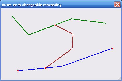
By moving the circular nodes, the length and angle of the segments can be changed; in this way the configuration of the whole bus is changed. The Form_FreeBuses.cs demonstrates two buses; one of them consists of a single segment while another has four segments (figure 20.35).

public Form_FreeBuses ()
{
    InitializeComponent ();
    mover = new Mover (this);
    bus_2 = new Bus (this, mover, new PointF (100, 100), new PointF (300, 200),
                     new Pen (Color .Green, 3));
    bus_5 = new Bus (this, mover,
          Auxi_Geometry .RandomPointsInsideRectangle (ClientRectangle, 20, 5),
                     new Pen (Color .Blue, 3));
    bus_2 .IntoMover (mover, 0);
    bus_5 .IntoMover (mover, 0);
}
Bus is a very simple object and has only three main parameters of visualization: color, width, and the type of line (DashStyle).
Two additional colors are used to show the end points and the joints between the connected segments; two Boolean parameters are used to switch the drawing
of these special points ON and OFF. In the Form_FreeBuses.cs neither the visualization parameters nor the number of segments in the buses can be changed
but all these things are going to be used in further examples.
The use of those two additional colors to mark all the movable points makes the changing of bus configuration much easier, but there are situations when such changes are not needed at all; in such case a bus can be shown without all additional marks. When user is already familiar with the way of changing the buses, these additional marks maybe not needed; in the FamilyTree application there is an easy way to switch them ON or OFF and user can do it at any moment.
public void Draw (Graphics grfx)
{
    … …
    grfx .DrawLines (m_pen, pts .ToArray ());
    if (bMarkJoints)
    {
        for (int i = 1; i < pts .Count - 1; i++)
        {
            Auxi_Drawing .FillEllipse (grfx, pts [i], 3, clrJoints);
        }
    }
    if (bMarkEnds)
    {
        Auxi_Drawing .FillEllipse (grfx, pts [0], 3, clrEnds);
        Auxi_Drawing .FillEllipse (grfx, pts [pts .Count - 1], 3, clrEnds);
    }
}
Menu position: Miscellaneous – Step by step to Family Tree – Free buses; adding joints
Two new things are added in the Form_FreeBuses_AddingJoints.cs and both of them can be seen in the code of the
OnMouseDown() method.
private void OnMouseDown (object sender, MouseEventArgs e)
{
    ptMouse_Down = e .Location;
     if (mover .Catch (e .Location, e .Button))
    {
        GraphicalObject grobj = mover .CaughtSource;
        if (e .Button == MouseButtons .Left)
        {
            if (grobj is Bus)
            {
                Bus bus = grobj as Bus;
                if (mover .CaughtNodeShape == NodeShape .Circle)
                {
                    bus .StartMoving (mover .CaughtNode);
                }
                else
                {
                    if (!bus .Movable)
                    {
                        int iSegment = mover .CaughtNode - bus .Points .Count;
                        PointF pt = bus .NearestPointOnSegment (e .Location,
                                                                iSegment);
                        mover .Release ();
                        bus .InsertPoint (iSegment + 1, pt);
                        Invalidate ();
                        mover .Catch (e .Location, e .Button);
                    }
                }
            }
        }
    }
}
The first change is the adjustment of the cursor position when the circular node is caught for movement.
if (mover .CaughtNodeShape == NodeShape .Circle)
{
    bus .StartMoving (mover .CaughtNode);
}
Inside the Bus.StartMoving() method the link between the mover and the caught bus is temporarily cut, the cursor is moved to the central point of the circular
node, and then the link is restored.
public void StartMoving (int iCircle)
{
    supervisor .MouseTraced = false;
    Cursor .Position = form .PointToScreen (Point .Round (pts [iCircle]));
        supervisor .MouseTraced = true;
}
From the moment of such initial correction and until the moment of the mouse release, the coordinates of the mouse cursor can be
used as the new location for the moved point (it can be one of the end points or one of the joints). This can be seen
in the Bus.MoveNode() method. I remind that the cover of a bus starts with the circular nodes and for the first half of the nodes the number of the node
is also the number of the point in the List<PointF>pts. The use of the
Bus.InformConnections() method inside the Bus.MoveNode() method will be explained later when we start working
with connected buses.
public override bool MoveNode (int i, int dx, int dy, Point ptM,
                                   MouseButtons catcher)
{
    bool bRet = false;
    if (catcher == MouseButtons .Left)
    {
        if (Movable)
        {
            Move (dx, dy);
            InformConnections (PositionUpdate .Soft, 0, pts .Count - 1);
        }
        else
        {
            if (i < pts .Count)
            {
                pts [i] = ptM;
                InformConnections (PositionUpdate .Soft, i - 1, i);
                bRet = true;
            }
        }
    }
    return (bRet);
}
The second interesting thing happens when some segment (not an end point and not a joint!) is pressed with a mouse.
private void OnMouseDown (object sender, MouseEventArgs e)
{
    … …
    if (!bus .Movable)
    {
        int iSegment = mover .CaughtNode - bus .Points .Count;
        PointF pt = bus .NearestPointOnSegment (e .Location, iSegment);
        mover .Release ();
        bus .InsertPoint (iSegment + 1, pt);
        Invalidate ();
        mover .Catch (e .Location, e .Button);
    }
By the number of the pressed node the number of segment is determined (iSegment); then the nearest point on this segment (pt) is calculated.
After it the mover is temporarily disconnected from the caught bus, the new joint is included into the bus at the calculated point, and the bus is
caught again but now by the circular node on this new joint. There was no joint before, but now the bus is caught by the joint; any joint is movable, so the reconfiguring of the bus can
go on. As you can see from the above code, such adding of the new joints is allowed only for the non-movable buses;
the next example demonstrates the difference in behaviour of movable and non-movable buses.
Menu position: Miscellaneous – Step by step to Family Tree – Free buses; changing movability
Look again at figure 20.33; even in such a simple tree of only several people there are buses with different types of connections.
- There are buses to give information about a couple and everyone understands that such bus cannot be moved freely to any other location because it has to show the link between two people and its ends must be always connected to the rectangles representing these people. If it is needed, this straight bus can be turned into a broken line with several joints, but at any moment it must show a link between those two people.
- There are short buses to connect one long bus with siblings. The rectangles for the siblings can be arbitrary placed on the screen and the bus to any of them can be much longer and may need to be turned into a broken line, but two ends of each bus are connected to some objects (a bus and a rectangle), so such bus cannot be moved freely around the screen.
- But there is one bus which ends are not fixed on any other objects. Other buses are connected to this bus and if you move this bus then all those connections must move also, but the ends of the bus itself are not fixed so this bus can be moved around without changing its view. This is the bus to which the siblings are connected. At figure 20.33 this bus is placed at the same distance from the rectangles showing two generations (between parents and their children). If anybody would prefer to move this bus closer to the rectangles of one generation or another he can easily do it without destroying the family tree. Well, this would be a good feature of design, but then there is a question of the way to do it because up till now the mouse press on the bus allowed only to add the new joint and to move this joint.
In all the examples of this book the forward movement of a whole object or any part of an object is done by the left button and I am not going to break this rule. In the previous example Form_FreeBuses_AddingJoints.cs the left button press at any inner point of a segment adds a joint at the pressed point and initiates the process of moving this new joint. Yet, we have a situation when, depending on our wish, such left button press must start either the adding and moving of the new joint or the move of the whole bus without any change in its configuration. The computer cannot screen user’s mind to determine what type of action this user plans to do at one moment or another, so some preliminary user’s action must determine it. This preliminary action is the change of movability of the bus.
Four pages back in the code of the bus constructor you can find such a line
Movable = false;
This flag – the movability feature of the bus – is
used in the Bus.DefineCover() method
to change some parameters of the bus cover and then the same feature is used in
the OnMouseDown() method of the form. The movability (or non-movability) of the bus
means whether the bus can be moved as the whole object without any changes or
not.
The cover of a bus consists of two sets of nodes:
- Circular nodes on joints and end points.
- Strip nodes along the segments.
public override void DefineCover ()
{
    … …
    for (int i = 0; i < nCircles; i++)
    {
        nodes [i] = new CoverNode (i, pts [i], rad);
    }
    for (int i = 0; i < nStrips; i++)
    {
        nodes [nCircles + i] = new CoverNode (nCircles + i, pts [i],
                                     pts [i + 1], rad, Behaviour .Frozen);
    }
    … …
}
By default any bus is non-movable; the behaviour of the circular nodes is not specified and it means that they get the default
value Behaviour.Moveable; the behaviour of the strip nodes is set to
Behaviour.Frozen. Together it means that:
- You can press any circular node (any joint or end point) and move it around the screen.
- You can press any
strip node as the mover feels all the frozen nodes but you cannot move
it. Instead, the new joint is
organized at the pressed point and, as any other joint, it is movable;
this was already explained in the previous example. This adding of the new joint is done
inside the
OnMouseDown()method but only if the pressed bus is non-movable (look at the code two pages back).
In the Form_FreeBuses_ChangingMovability.cs you can call the small context menu on any segment of a bus; this menu contains only one command which allows to change the movability of the pressed bus.
private void Click_miMovable (object sender, EventArgs e)
{
    busPressed .Movable = !busPressed .Movable;
    busPressed .MarkEnds = !busPressed .Movable;
    busPressed .MarkJoints = !busPressed .Movable;
    Invalidate ();
}
When the movability of the bus is changed, its cover is redefined; the number and order of nodes is not changed, but their behaviour changes.
public override void DefineCover ()
{
    … …
    if (Movable)
    {
        cover .SetBehaviour (NodeShape .Circle, Behaviour .Frozen);
        cover .SetBehaviour (NodeShape .Strip, Behaviour .Moveable);
    }
}
In the movable bus, all the circular nodes are frozen while the strip nodes are movable. This means that there is no more way to add new joints because
it is allowed in the OnMouseDown() method only for non-movable buses. At the same time the
Bus.MoveNode() method works as usual.
public override bool MoveNode (int i, int dx, int dy, Point ptM,
                                       MouseButtons catcher)
{
    bool bRet = false;
    if (catcher == MouseButtons .Left)
    {
        if (Movable)
        {
            Move (dx, dy);
            InformConnections (PositionUpdate .Soft, 0, pts .Count - 1);
        }
        … …
For a movable bus the MoveNode() method calls the Move() method in which all the points are
moved synchronously; as a result, the whole bus is moved without changing its
configuration.
public override void Move (int dx, int dy)
{
    Size size = new Size (dx, dy);
    for (int i = 0; i < pts .Count; i++)
    {
        pts [i] += size;
    }
}
The reaction on the left button press is absolutely different for movable and non-movable buses and it would be a real confusion for users if the movable and non-movable buses would look identically. To avoid such confusion, the view of the bus slightly changes depending on its movability. For non-movable buses the joints and end points are marked by special colors; this makes the catching and moving of such special points easier. For movable buses these special colors disappear; the whole bus is painted by one color; there are no visible special points and this emphasizes that the whole bus is an object to be moved without changing of configuration.
In the real Family Tree application more changes in view and configuration of buses can be needed; these possible changes are tested in the next example.
File: Form_FreeBuses_AllPossibleChanges.cs
Menu position: Miscellaneous – Step by step to Family Tree – Free buses; all possible changes
Parameters of the buses in the Form_FreeBuses_AllPossibleChanges.cs can be changed via the commands of context menus. Two context
menus are used in this form: one can be called on the joints of the buses, another – on segments. As usual, the menu to be called is determined in the OnMouseUp() method
of the form and the decision is based on the shape of the pressed node. At the same moment the number of the pressed joint or segment is determined by the number of the pressed node.
private void OnMouseUp (object sender, MouseEventArgs e)
{
    int iWasObject, iWasNode;
    NodeShape shapeNode;
    ptMouse_Up = e .Location;
    if (mover .Release (out iWasObject, out iWasNode, out shapeNode))
    {
        if (e .Button == MouseButtons .Right && mover.WasCaughtSource is Bus &&
            Auxi_Geometry .Distance (ptMouse_Down, ptMouse_Up) <= 3)
        {
            busPressed = mover .WasCaughtSource as Bus;
            if (shapeNode == NodeShape .Strip)
            {
                iPressedSegment = iWasNode - busPressed .Points .Count;
                ContextMenuStrip = menuOnSegment;
            }
            else
            {
                iPressedPoint = iWasNode;
                ContextMenuStrip = menuOnJoint;
            }
        }
    }
}
Menu on joints (menuOnJoint) contains a single command to delete the pressed joint; when executed it allows
to straighten the bus without moving the joints manually. In this Form_FreeBuses_AllPossibleChanges.cs
the removal of the joints is allowed both for movable and non-movable buses, but there are some doubts about the correctness of applying this command to the
movable buses. When the bus is declared movable, then it can be moved around the screen without any changes in view and
the possibility of adding new joints is also eliminated. Two features of a bus – the movability and the possibility of its reconfiguring – to some extent associate with each other
and there can be different views on the rigidity of their correlation.
- If you look at the change of the bus movability only as the chance to move the whole object, then the possibility to erase the joints of such bus is correct.
- If you think that for movable buses all the possibilities of changing their configuration must be blocked, then this command for movable buses must be disabled.
Anyway, if you prefer the second point of view, then you can add a couple of code lines into the
OnMouseUp() method and allow to call the menuOnJoint only for the non-movable buses.
Menu which is called on segments has several commands (figure 20.36).

Movable (bus) allows to switch the movability of the pressed bus between ON and OFF. The change of movability slightly changes the
view of the bus as was explained in the previous example.
Tuning (bus) calls an additional tuning form to modify the view of the pressed bus; the
Form_Tuning_Bus.cs is shown at
figure 20.37. In this form you can change the color, width, and type (DashStyle) of the line; you can also change the additional colors for end points and joints.

- Remove all joints (inside bus) erases all the joints and leaves the bus consisting of a single segment between the end points.
- Horizontal (segment) changes the angle of the pressed segment and turns it into horizontal line.
- Vertical (segment) changes the angle of the pressed segment and turns it into vertical line.
The two last commands work in the similar way and have similar limitations of their use.
- Both ends of a bus
look similar and it is impossible to determine visually from which of them
the order of points starts, but all the points are placed in the
List<PointF>ptsin some order and on using one of these commands the next of two points is moved. This is correct for any segment except the last one for which the previous point is moved. - If the pressed segment is nearly horizontal and you order to turn it into a vertical line, then two of its end points get the same X coordinate and the new segment will be very short. If you apply the same command to the horizontal segment, it will turn into a single point and disappear from view. To avoid such situations; the command is allowed only for segments which will turn into a new segment with the length not less than 10 pixels. Similar limitation works for another command of the pair.
Up till now we were looking at the free buses which were not connected to anything. In the real family tree we do not have absolutely free buses; any bus in the family tree is connected to one or several objects. Figure 20.30 shows that buses are either connected to each other or can be used as the links between the rectangles associated with people. We will deal with the second variant a bit later and now let us work on the problem of connected buses.
Buses are not connected to each other by the arbitrary points. On the contrary, there is only one way to organize any bus connection and there are strict rules on how this connection works after it. The only way to organize a connection between two buses is to move and end point of one bus and to fix it in some way on another bus. From this moment the end point of the first bus can move only along the second bus using it as a rail. It does not matter whether the second bus is a straight or a broken line; the connected end of the first bus can move only along the second bus between its end points.
An additional class BusConnection is used to organize a connection between two buses.
public class BusConnection : GraphicalObject
{
    Form form;
    Mover supervisor;
    PointF pt;
    int m_radius;
    Bus m_busOfEnd;
     EndType end_type;
    Bus m_busRail;
    int iSegment;
    double coefOnSegment;
An object of the BusConnection class is organized at the end point of the bus which
is going to be connected to another bus.
To organize a new connection, some information about both buses is
needed. This information includes the
point of connection (pt), the radius of the sensitive area of connection (m_radius), the bus which is connected by its end point (m_busOfEnd), the value which specifies the exact end of this bus
(end_type), and another bus to which the first one is connected
(m_busRail).
public BusConnection (Form frm, Mover mvr, PointF point, int rad, Bus bus_End,
                          EndType endType, Bus bus_Rail)
{
    form = frm;
    supervisor = mvr;
    m_radius = Math .Max (Math .Abs (rad), 3);
    m_busOfEnd = bus_End;
    end_type = endType;
    busRail = bus_Rail;
    pt = Auxi_Geometry .NearestPointOnPolyline (point, busRail .Points,
                                   out dist, out iSegment, out coefOnSegment);
}
The preliminary calculated point of connection, passed
as a parameter to constructor, can be not very accurate; you can pass even an
arbitrary point as a parameter. In any case
the real point of connection – the real point on the bus (pt), which is the closest to the one passed as a
parameter, is calculated in the constructor.
The same method returns the segment of connection (iSegment) and the positioning coefficient for the point of
connection on this segment (coefOnSegment). The cover of this new object consists of a
single circular node.
public override void DefineCover ()
{
    cover = new Cover (new CoverNode (0, pt, m_radius));
}
The next example shows the design and use of the connection between two buses.
File: Form_ConnectedBuses_Two.cs
Menu position: Miscellaneous – Step by step to Family Tree – Two connected buses

Even the name of the example informs that there are two connected buses in the Form_ConnectedBuses_Two.cs (figure 20.38). First the green bus is organized, then the blue one.
public Form_ConnectedBuses_Two ()
{
    … …
    busGreen = new Bus (this, mover, points, new Pen (Color .Green, 3));
    … …
    busBlue = new Bus (this, mover, points, new Pen (Color .Blue, 3));
For both of them the constructor uses only the color and points, so they do not know anything about each other. If nothing else is done, these two buses behave like absolutely independent objects; we already have such an example.
Next steps are:
- To construct a
BusConnectionobject at the end of the blue bus.
con = new BusConnection (this, mover, pt, busBlue .NodeRadius, busBlue, EndType .Head, busGreen);
busGreen .AddConnection (con);
busGreen .IntoMover (mover, 0);
busBlue .IntoMover (mover, 0);
con .IntoMover (mover, 0);
Now let us look in details how this connection works.
Three objects are included into the mover’s queue: two buses and one BusConnection object. This object is at the head of the queue and
it covers the starting point of the blue bus. Thus, when you press with the left button on the point of connection not the end point of the blue bus is caught but this
BusConnection object.
private void OnMouseDown (object sender, MouseEventArgs e)
{
    if (mover .Catch (e .Location, e .Button))
    {
        GraphicalObject grobj = mover .CaughtSource;
        if (e .Button == MouseButtons .Left)
        {
            … …
            else if (grobj is BusConnection)
            {
                (grobj as BusConnection) .StartMoving ();
            }
        … …
When this BusConnection object is caught, the BusConnection.StartMoving()
method is called and the same sequence of
steps is done as when any circular node of a bus is caught: the link between
the mover and the caught object is cut, the mouse cursor is moved to the
central point of the node, and then the link is restored.
public void StartMoving ()
{
    supervisor .MouseTraced = false;
    Cursor .Position = form .PointToScreen (Point .Round (pt));
    supervisor .MouseTraced = true;
}
The possible movements of the caught connection are
described by the BusConnection.MoveNode() method.
public override bool MoveNode (int i, int dx, int dy, Point ptM,
                                       MouseButtons catcher)
{
    bool bRet = false;
    if (catcher == MouseButtons .Left)
    {
        Location = ptM;
        supervisor .MouseTraced = false;
        Cursor .Position = form .PointToScreen (Point .Round (pt));
        supervisor .MouseTraced = true;
    }
    return (bRet);
}
Visually it looks as if from the moment when the
connection point is pressed and until the mouse is released it can move only
along the bus on which the connection point is placed and at any moment the
connection point goes with the mouse cursor.
In reality it works vice versa and the code of the BusConnection class determines the possible movements of the mouse
cursor.
Mouse is moved to some position and with very high
probability it is not on the bus but somewhere aside; then the BusConnection.Location
property adjusts the position of the
connection to the nearest point on the bus along which the connection point has
to move, and the connected end of the bus is moved to the same point. Thus, regardless of any movement, the
BusConnection object covers this end of the bus.
public PointF Location
{
    get { return (pt); }
    set
    {
        pt = Auxi_Geometry .NearestPointOnPolyline (value, busRail .Points,
                                out dist, out iSegment, out coefOnSegment);
        DefineCover ();
        if (end_type == EndType .Head)
        {
            m_busOfEnd .HeadPoint = pt;
        }
        else
        {
            m_busOfEnd .TailPoint = pt;
        }
    }
}
After it the mouse cursor is moved to the same point;
for this cursor movement there is again the temporary cut of the link between
the mover and the caught object (look at the BusConnection.MoveNode()
method on the previous page).
In this way the point of connection is moved only along the green bus and the connected end of the blue bus moves with this point. But what happens when the configuration of the green bus is changed? How the end of the blue bus keeps its connection to the green bus throughout its movement?
I have mentioned on the previous page that when the connection between two buses was organized the information about the connected bus (the blue one) was passed to the bus with which it was connected (the green one).
busGreen.AddConnection (con);
Any bus keeps the track of all its “side” connections. There are two separate lists for connections of heads and tails; the BusConnection.AddConnection() method
adds a new element to the appropriate list.
public void AddConnection (BusConnection cnct)
{
    if (cnct .ConnectionType == EndType .Head)
    {
        headsConnected .Add (cnct);
    }
    else
    {
        tailsConnected .Add (cnct);
    }
}
Green bus at figure 20.38 consists of three segments; there are four points with numbers 0, 1, 2, and 3 going from left to right; the blue bus is connected at segment one
between points 1 and 2. Now let us press and move the point number 1 – the second point of green bus from the left. When the joint of any bus is pressed and
moved then the Bus.MoveNode() method is called. The code of this method was already shown several pages back; at the moment we are interested only in that
part of the method which deals with moving of the joints.
public override bool MoveNode (int i, int dx, int dy, Point ptM,
                                   MouseButtons catcher)
{
    … …
    if (i < pts .Count)
    {
        pts [i] = ptM;
        InformConnections (PositionUpdate .Soft, i - 1, i);
        bRet = true;
    }
When any bus is moved or reconfigured, some or all of
the connections on this bus must adjust their positions. First, there are two types of adjustment;
this is regulated by the enumeration PositionUpdate. Imagine the
situation (it is real, but we did not look at such case yet) when the bus is
moved without any change of its configuration and all the connections must
retain their relative positions. This
means that each connection is still positioned on the same segment and with the
same positioning coefficient along the segment.
Thus, only the absolute screen position of the connection is changed
because the bus has moved; such change of position is described as PositionUpdate.Soft. Another
situation happens when all the joints of a bus are deleted, the bus, which
could be a broken line, turns into straight line, and all the connections have
to be positioned on this new bus.
Certainly, there are no questions of gaining the number of segment and
the positioning coefficient; both values must be recalculated; this situation
is described as PositionUpdate.Hard.
When the whole bus is moved, then all its connections
must be relocated. When any joint is
moved, only the segments on both sides of this joint are changed and only the
connections on these segments must be relocated; all other connections behind
the neighboring joints are not disturbed at all. Thus, it would be enough to inform about the
movement of any joint only the connections on the neighboring segments, but
another logic is used in the Bus.MoveNode() method. As seen
from the code, all the connections are informed, so it is for each connection
to decide whether it has to react on the movement of a particular joint or not.
public void InformConnections (PositionUpdate updateType, int iSeg_0, int iSeg_1)
{
  foreach (BusConnection connection in headsConnected)
  {
      connection .RailChanged (updateType, iSeg_0, iSeg_1);
  }
  foreach (BusConnection connection in tailsConnected)
  {
      connection .RailChanged (updateType, iSeg_0, iSeg_1);
  }
}
Parameters that are passed to the Bus.InformConnections()
method include the type of adjustment (updateType) and the range of the involved segments (from
iSeg_0 to iSeg_1). The same set of parameters is passed to each
of the connections to the method BusConnection.RailChanged(). This method
has to calculate the new position of connection in reaction to the change of
the bus on which it is positioned; any calculation is needed only if the
particular connection is situated on a segment inside the specified range. If the connection has to be moved, then its
new position depends on the type of the adjustment. If it is the PositionUpdate.Soft adjustment,
then the number of the segment and the positioning coefficient inside the
segment retain their values and the new point is calculated using these
unchanged values. For the case of the PositionUpdate.Hard adjustment, the new position is
calculated using only the points of the bus, while the new segment number and
the positioning coefficient along this segment are the additional results of
this calculation.
public void RailChanged (PositionUpdate updateType, int iSeg_0, int iSeg_1)
{
    if (iSeg_0 <= iSegment && iSegment <= iSeg_1)
    {
        PointF ptNew;
        if (updateType == PositionUpdate .Soft)
        {
            ptNew = Auxi_Geometry .PointOnLine (busRail .Points [iSegment],
                               busRail .Points [iSegment + 1], coefOnSegment);
        }
        else
        {
            ptNew = Auxi_Geometry .NearestPointOnPolyline (pt, busRail .Points,
                                      out dist, out iSegment, out coefOnSegment);
        }
        Location = ptNew;
    }
}
The calculated position is passed to the BusConnection.Location property where two things happen: the connection
is relocated to this new position and then this value is sent to one or another property of the connected bus; the exact property depends on whether that bus
is connected by the first or by the last of its points.
public PointF Location
{
    get { return (pt); }
    set
    {
        pt = Auxi_Geometry .NearestPointOnPolyline (value, busRail .Points,
                                    out dist, out iSegment, out coefOnSegment);
        DefineCover ();
        if (end_type == EndType .Head)
        {
            m_busOfEnd .HeadPoint = pt;
        }
        else
        {
            m_busOfEnd .TailPoint = pt;
        }
    }
}
If the head of another bus is connected at this point, then the Bus.HeadPoint property changes the first point of that bus.
public PointF HeadPoint
{
    get { return (pts [0]); }
    set { ChangePoint (0, value); }
}
If there are some connections on that second bus, then the Bus.ChangePoint() method not only relocates the first point of the bus but also disturbs all the
connections; eventually this disturbance will die somewhere, but on the way all the involved connections and bus ends will take their new positions.
public void ChangePoint (int iPoint, PointF pt)
{
    if (0 <= iPoint && iPoint < pts .Count)
    {
        pts .RemoveAt (iPoint);
        pts .Insert (iPoint, pt);
        DefineCover ();
        InformConnections (PositionUpdate .Soft, iPoint - 1, iPoint);
    }
}
Now we have the full picture of what happens when one or another point of the green bus is caught and moved. In situation from figure 20.38 there are going to be different results when the second from the left or the right point of the green bus are moved. Let us look at the details of both cases.
If the second from the left point of the green bus is caught and the mouse is moved, then:
- The mouse is moved
somewhere (
ptM). By theBus.MoveNode()method the caught joint ( i == 1 ) is moved to the same point as the mouse and all the connections of the green bus are informed that two segments of the bus has changed. - The green bus has only one connection and for it the
BusConnection.RailChanged()method is called with the same parameters. - Our connection happens to be inside the specified range of segments (
iSegment == 1), so the new position for connection is calculated as a soft adjustment and then this new position is passed to theBusConnection.Locationproperty. - The
BusConnection.Locationproperty changes the real location of the connection point and sends this new location to the blue bus to be used in theBus.HeadPointproperty. - The Bus.HeadPoint property changes the position of the first point of the blue bus and then the disturbance is over because there are no connections on the blue bus.
pts [1] = ptM;
InformConnections (PositionUpdate .Soft, 0, 1);
connection.RailChanged (PositionUpdate .Soft, 0, 1);
ptNew = Auxi_Geometry .PointOnLine (busRail .Points [1], busRail .Points [2], coefOnSegment);
Location = ptNew;
pt = Auxi_Geometry .NearestPointOnPolyline (value, busRail .Points, out dist, out iSegment, out coefOnSegment);
m_busOfEnd .HeadPoint = pt;
When the right point of the green bus is caught and the mouse is moved, then the chain of events is shorter:
- The mouse is moved somewhere (
ptM). By theBus.MoveNode()method the caught joint (i == 3) is moved to the same point as the mouse and all the connections of the green bus are informed that two segments of the bus has changed. - The green bus has only one connection and for it the
BusConnection.RailChanged()method is called with the same parameters. - The connection on the green bus is outside the specified range (
iSegment == 1), so nothing has to be done. In situation from figure 20.38 the movement of the right point of the green bus has no effect on connection.
pts [3] = ptM;
InformConnections (PositionUpdate .Soft, 2, 3);
connection.RailChanged (PositionUpdate .Soft, 2, 3);
We already saw that whenever an end point or any joint of a bus is moved, the Bus.InformConnections() method must be called.
Next examples will demonstrate several situations when this method must be called and there is a very simple logic to determine the set of needed parameters for such call.
- If an end point or a joint is moved by a mouse, then the relative position of any connection on
that bus is not changed; this means the use of the
PositionUpdate.Softparameter. As a result of the mentioned movement not more than two consecutive segments are changing, so two consecutive numbers represent the range of changing segments. For an end point only one segment is changed, but for the simplicity of the code the range of segments is still represented by two consecutive numbers. One of the mentioned segments does not exist, but this is not a problem at all as no connection can be positioned on a non-existing segment, so no action will be done for this non-existing segment. - If the number of joints is changed, then it is always the
PositionUpdate.Hardparameter and all the segments must be included into the range.
One of the cases that fall into second variant is the addition of the new joint when any segment is pressed with the left button; in
this case the call to the Bus.InformConnections() method is included into the
OnMouseDown() method.
File: Form_ConnectedBuses_Three.cs
Menu position: Miscellaneous – Step by step to Family Tree – Three connected buses

In the next example – the Form_ConnectedBuses_Three.cs – we have three buses and one of them is connected to others on both ends (figure 20.39). This example allows to check the correctness of work for connections on both ends of a bus while everything else is nearly the same as in the previous example.
Beginning from this example and further on until the
development of the real Family Tree
application there are going to be a lot of bus connections. In some cases only one end of a bus is
connected to something; in other cases a bus is connected by its both
ends. For all these situations the ConnectedBus() method can be very useful; this method constructs the
new bus and all the needed connections.
The same method could be used in the previous example, but I decided to
postpone its use until this Form_ConnectedBuses_Three.cs.
public Bus ConnectedBus (Form frm, Mover mvr, Pen pn, Bus busHeadConnected,
         Bus busTailConnected, List<PointF> points, out List<BusConnection> cons)
{
    List<BusConnection> newcons = new List<BusConnection> ();
    int iLast = points .Count - 1;
    if (busHeadConnected != null)
    {
        points [0] = Auxi_Geometry .NearestPointOnPolyline (points [0],
                                                     busHeadConnected .Points);
    }
    if (busTailConnected != null)
    {
        points [iLast] = Auxi_Geometry .NearestPointOnPolyline (points [iLast],
                                                     busTailConnected .Points);
    }
    Bus bs = new Bus (frm, mvr, pn, points);
    if (busHeadConnected != null)
     {
        BusConnection conHead = new BusConnection (frm, mvr, points [0],
                    Math .Max (busHeadConnected .NodeRadius, bs .NodeRadius),
                                         bs, EndType .Head, busHeadConnected);
        busHeadConnected .AddConnection (conHead);
        newcons .Add (conHead);
    }
    if (busTailConnected != null)
    {
        BusConnection conTail = new BusConnection (frm, mvr, points [iLast],
                    Math .Max (busTailConnected .NodeRadius, bs .NodeRadius),
                                         bs, EndType .Tail, busTailConnected);
        busTailConnected .AddConnection (conTail);
        newcons .Add (conTail);
    }
    cons = newcons;
    return (bs);
}
You can check one more interesting effect with the buses. Change one bus, for example, the green one in such a way that it will turn into a closed loop. This is easy to do as any number of joints can be added to the bus by simple left button press on the bus and the length of segments can be changed by moving the joints and end points. At the end of all changes move one end point of a bus on top of another. If you turn the green bus into a closed loop, then the connected end point of the brown bus can move without problems around such loop. You can even put two end points of the green bus somewhere close to each other and the existence of the small gap will be not a problem. If the green bus is reconfigured in such a way as to cross itself, then the end point of the brown bus will jump from one segment to another. For the Family Tree application there is no need in adding any special checking to prevent such jumps from one segment of the bus to another.
I cannot imagine a situation when anyone would need to change the bus in such a way that it will cross itself, but the case of a bus in a form of a closed loop is different. The bus in a form of a closed loop is not only a funny exercise. A bit later you will see that it is a very useful element.
File: Form_ConnectedBuses_ChangingMovability.cs
Menu position: Miscellaneous – Step by step to Family Tree – Connected buses; changing movability
In the new example, there are the same three buses connected in the same way, but I added a small menu containing one command to change the movability of the pressed bus. Well, this command can be applied not to every bus, so it is allowed for the green and blue buses but not for the brown bus. Certainly, this exclusion is not based on the bus color. I have already explained before that movability can be changed for the buses with the free ends while the connected buses cannot be movable.
By default all three buses are non-movable and when you press with the left button any segment of the green bus, then the new joint of this green bus appears under the cursor. You continue to move this new joint and the connected point of the brown bus moves only if it happens to be in the segment next to this joint.
Now call the context menu on the green bus (as usual, the right button click will do it) and turn the green bus into movable. The view of the green bus will change a bit to indicate the movability of the bus; this disappearance of the special colored marks for the end points and joints (figure 20.40) was already mentioned before.
When you press with the left button this movable green bus, no new joint appears under the cursor, but instead the whole bus starts moving around the screen and the connected point of the brown bus moves with it regardless of the segment to which it is connected and of the point where you grabbed the green bus. What chain of methods works in this situation?
First, the Bus.MoveNode() method for the pressed bus is called. As you can see from the code, for the movable
bus regardless of the pressed node this method calls the Bus.Move()
method and thus the whole bus is
moved. After it all the connections on
the bus are informed about the change of points throughout the InformConnections() method and in this case the range of changed segments
includes all the segments. This means
that all the connections will adjust their positions and with them the end
points of all the connected buses.
public override bool MoveNode (int i, int dx, int dy, Point ptM,
                                       MouseButtons catcher)
{
    bool bRet = false;
    if (catcher == MouseButtons .Left)
    {
        if (Movable)
        {
            Move (dx, dy);
            InformConnections (PositionUpdate .Soft, 0, pts .Count - 1);
        }
        … …
At the same time the type of adjustment is PositionUpdate.Soft. The bus is moved around the screen without any change of its configuration, so all points
of connection retain their numbers of segments to which they are connected and positioning coefficients inside those segments.
File: Form_ConnectedBuses_AllPossibleChanges.cs
Menu position: Miscellaneous – Step by step to Family Tree – Connected buses; all possible changes
This example demonstrates all possible changes that can be applied to connected buses. The connected buses in this example are similar to what was used in the previous example; the changes allowed for the buses are the same that were demonstrated for free buses in the Form_FreeBuses_AllPossibleChanges.cs example. To start all the needed changes, the same two context menus are used. Menu to be called on any joint consists of a single command line to delete the pressed joint.
Menu on segments contains the same five commands which were explained nine pages back (figure 20.36). While writing about the commands to turn the pressed segment into vertical or horizontal, I mentioned some limitations but I forgot to mention one thing. These two commands – to turn a segment into vertical or horizontal – can move, if other limitations allow, one of the joints of a bus but they never move end points. Because of this limitation, the logic of these commands for the last segment of a bus slightly differs from the logic of applying these commands to any other segment. This restriction on moving any end point by these two commands also do not allow to apply these commands to any bus consisting of a single segment.
I think that the buses to be used in the Family Tree are now developed and tested and it is time to look at another important element of any family tree – at the rectangle representing a person.
Any person in the family tree is represented by an object of the Person class. On the screen such object is shown as a
rectangular area with some additional information. The rectangle is movable and resizable (did you expect anything else?); the information is organized in the form
of three CommentToRect objects associated with this rectangle.
public class Person : GraphicalObject
{
    Form form;
    RectangleF rc;
    SolidBrush m_brush;
    Pen penBorder = new Pen (Color .DarkGray);
    CommentToRect cmntName = null;
    CommentToRect cmntBirth = null;
    CommentToRect cmntDeath = null;
    Bus busOnBorder;
One comment shows the name of the person; this comment
– cmntName – always exists.
Even if you do not know the name of the person, you can call him Unknown or anything else, but you cannot
organize a Person object
without this comment. Two other comments
are not mandatory. For the living person
the information about his death is rarely known, so in this case the cmntDeath is not needed.
It is not a rare case when for a relative several generations back the
DOB information is not known. It is
possible to put some date (year) with a question or simply omit this cmntBirth.
File: Form_Person.cs
Menu position: Miscellaneous – Step by step to Family Tree – Person

The class Person has several constructors; the Form_Person.cs demonstrates maybe the most often used of them which produces an object with
all three comments in view (figure 20.41).
public Form_Person ()
{
    InitializeComponent ();
    mover = new Mover (this);
    person = new Person (this, new RectangleF (150, 150, 210, 60), Color .Cyan,
                         "James", "3-Oct-1916", "23-Feb-1995");
    person .IntoMover (mover, 0);
}
The standard feature of any user-driven application is that the choice of information to be shown and its view is the prerogative of the user. If there is an object on the screen, then there must be an easy way to change its view; in the Form_Person.cs you can call the context menu on the Person object and via its only command open an additional tuning form to change the view of the pressed object (figure 20.42).

The Form_Tuning_Person.cs allows to change the background color of the rectangle and to modify all three comments. For each of these comments the text color and the font can be set individually. There are no strict rules on how the birth and death information must be shown; these are only the strings and you can type anything there. If you clear the information from the text boxes for birth and death then those comments will not appear in the Person object. If you try to do the same with the text box for a name then the word Unknown will appear instead of the name.
The graphical object inside the Form_Tuning_Person.cs is also a Person object, so the comments of this object can be moved around the screen, but the position of these comments in the tuning form will not change the positions of the comments of the modified object. This was purposely done for tuning of a single Person object because in the same easy way the comments of the modified object can be moved. Further on, in the real Family Tree application, you will see a similar tuning of the Person object that is used as a sample for all others and for that case the positioning of comments in the tuning form will determine their positions in the new Person objects.
Any Person object
is a complex object and its parts can be involved in individual, related, and
synchronous movements.
- Any comment can be moved individually.
- When the main colored rectangle is moved then all its associated comments move synchronously.
- When the colored rectangle is resized then the associated comments retain their relative positions.
As any other complex object, the Person object has to be registered with the mover not by
Mover.Add()
or Mover.Insert() methods but by its Person.IntoMover() method which registers in the correct order the main
rectangle and all its associated comments.
new public void IntoMover (Mover mover, int iPos)
{
    if (iPos < 0 || mover .Count < iPos)
    {
        return;
    }
    mover .Insert (iPos, this);
    mover .Insert (iPos, cmntName);
    if (cmntBirth != null)
    {
        mover .Insert (iPos, cmntBirth);
    }
    if (cmntDeath != null)
    {
        mover .Insert (iPos, cmntDeath);
    }
}
Among the fields of the Person class (two pages back) you can see one field which was not mentioned up till now:
Bus busOnBorder;
When any Person object is initialized, its busOnBorder field is also initialized; this is done inside the
Person.GeneralInitialization_WithoutName() method.
private void GeneralInitialization_WithoutName (Form frm, RectangleF rect,
                                                    Color clr)
{
    form = frm;
    rc = new RectangleF (rect .Left, rect .Top,
                         Math .Max (rect .Width, minSide),
                         Math .Max (rect .Height, minSide));
    busOnBorder = new Bus (form, null, Auxi_Geometry .BorderOfRectangle (rc),
                           penBorder);
    busOnBorder .MarkEnds = false;
    busOnBorder .MarkJoints = false;
    busOnBorder .RegisteredWithMover = false;
    m_brush = new SolidBrush (clr);
}
The points of the new bus – busOnBorder – are prepared by the
Auxi_Geometry.BorderOfRectangle() method which returns the List<PointF>. This List contains the coordinates of the corners of rectangle,
but there are not four but five elements in this List;
the first and the last elements are the same.
Thus, the busOnBorder is organized as a closed
loop.
The Person object is a complex object which has one main element
and several other elements associated with this one. When the main element – a rectangle – is
resized or moved, all the associated elements must be informed about the change
of the main element; this is done by the Person.InformRelatedElements()
method.
All the associated comments (from one to three, depending on the
particular situation) adjust their positions by using the standard CommentToRect.ParentRect
property; the busOnBorder gets the new points by calling again the
Auxi_Geometry.BorderOfRectangle() method.
Thus, the busOnBorder is always a closed loop
regardless of any changes of the rectangular area.
private void InformRelatedElements ()
{
    Rectangle rect = Rectangle .Round (rc);
    cmntName .ParentRect = rect;
    if (cmntBirth != null)
    {
        cmntBirth .ParentRect = rect;
    }
    if (cmntDeath != null)
    {
        cmntDeath .ParentRect = rect;
    }
    busOnBorder .Points = Auxi_Geometry .BorderOfRectangle (rc);
}
Neither joints nor the end points of the busOnBorder are marked by special colors:
busOnBorder.MarkEnds = false;
busOnBorder .MarkJoints = false;
When any Person object is shown on the screen, its bus along the border is not shown;
the busOnBorder field is not even mentioned in the Person.Draw() method.
public void Draw (Graphics grfx)
{
    grfx .FillRectangle (m_brush, rc);
    grfx .DrawRectangle (penBorder, Rectangle .Round (rc));
    cmntName .Draw (grfx);
    if (cmntBirth != null)
    {
        cmntBirth .Draw (grfx);
    }
    if (cmntDeath != null)
    {
        cmntDeath .Draw (grfx);
    }
}
In the previous examples we did a lot of things with the Bus objects and we saw how they could be
moved and changed. With the help of the BusConnection objects, buses can be organize into a system of
connected buses which we are going to use in our Family Tree application. But as you can see from the code of the
Person.IntoMover() method, this field busOnBorder is
not even mentioned in the method, so mover does not know anything about the existence of this field. Yet, this is the field
which allows to design the whole family tree. To understand the role and the importance of the
busOnBorder field let us look at the next very simple example in
which there is a single Person object and only one additional bus connected to it.
File: Form_PersonPlusBus.cs
Menu position: Miscellaneous – Step by step to Family Tree – Person with connected bus

There are only one person and one visible bus in the Form_PersonPlusBus.cs (figure 20.43). This bus has one of its end points on the border of the Person object; if you press this end point with the left button and try to move it anywhere, you will immediately find out that it will move only along the border and nowhere else. Does it look familiar to you? Does it look like moving the end of the bus along another bus with which it is connected?
Yes, this is exactly what happens when a bus is connected to a Person object: in reality a bus is connected to a
busOnBorder – an invisible bus that goes along the border. It does not matter at all that one of two involved buses is invisible; the connection between a bus
and a Person object is organized in the same way as between the buses, for example, in the Form_ConnectedBuses_Two.cs.
There are only one person and one shown bus in the Form_PersonPlusBus.cs (figure 20.43), but this is the first example in which we have all three types of elements on which the real Family Tree application will be designed. Elements of three classes are organized into three separate lists and in the next several more complex examples you will see exactly the same organization of all the elements.
public partial class Form_PersonPlusBus : Form
{
    Mover mover;
    List<Person> people = new List<Person> ();
    List<Bus> buses = new List<Bus> ();
    List<BusConnection> connections = new List<BusConnection> ();
When the Form_PersonPlusBus.cs starts, at first the Person object is designed.
public Form_PersonPlusBus ()
{
    InitializeComponent ();
    mover = new Mover (this);
    Person person = new Person (this, new RectangleF (100, 100, 140, 60),
                                Color .Cyan, "Unknown");
    AddPerson (person);
When any new object of the Person, Bus, or BusConnection class
is organized, it is added to the end of the corresponding List. It is a bit
more complicated with the construction of new Person object because it also contains the new bus; thus, the
AddPerson() method calls the AddBus() method
and eventually increases not one but two Lists.
private void AddPerson (Person prsn)
{
    … …
    people .Add (prsn);
    AddBus (prsn .Bus);
}
  private void AddBus (Bus busNew)
{
    … …
    buses .Add (busNew);
}
When the bus is organized in the Form_PersonPlusBus.cs, it gets, among other parameters, the list of points. This is not a free bus, but it must
be connected to the bus on border of the Person object. Thus, with very high probability one of its points must be adjusted and then the
BusConnection object must be organized at this corrected point. All these things are done in the BusFromPerson() method.
public Form_PersonPlusBus ()
{
    … …
    List<PointF> points = new List<PointF> ();
    points .Add (new PointF (220, 160));
    points .Add (new PointF (270, 210));
    points .Add (new PointF (410, 120));
    BusConnection con;
    Bus bus = BusFromPerson (this, mover, new Pen (Color .Blue, 3), person,
                             points, out con);
    AddBus (bus);
    AddConnection (con);
    RenewMover ();
}
private Bus BusFromPerson (Form frm, Mover mvr, Pen pn, Person person,
                           List<PointF> points, out BusConnection con)
{
    Bus busFrom = person .Bus;
    points [0] = Auxi_Geometry .NearestPointOnPolyline (points [0],
                                                        busFrom .Points);
    Bus bs = new Bus (frm, mvr, points, pn);
    con = new BusConnection (frm, mvr, points [0], bs .NodeRadius, bs,
                             EndType .Head, busFrom);
    busFrom .AddConnection (con);
    return (bs);
}
After all elements are organized and included into the corresponding lists, we have such filling of those lists:
List<Person>people contains one element.List<Bus>buses contains two elements; one of them is seen at figure 20.43 while another is invisible and goes along the border of the Person object.List<BusConnection>connections contains one element.
Mover can work with elements of all three mentioned classes, so all of them must be registered with the mover but registered in the correct
order: BusConnection elements must precede all the Bus elements and they must precede all the
Person elements.
private void RenewMover ()
{
    mover .Clear ();
    foreach (Person person in people)
    {
        person .IntoMover (mover, 0);
    }
    foreach (Bus bus in buses)
    {
        bus .IntoMover (mover, 0);
    }
    foreach (BusConnection con in connections)
    {
        con .IntoMover (mover, 0);
    }
}
We have two buses in the Form_PersonPlusBus.cs: one is perfectly visible at figure 20.43 and another one is
invisible and goes along the border of the Person object. Both buses are included into the
List of buses and the code of the RenewMover() method
shows that for each bus from the List the Bus.IntoMover() method is called.
At the same time I already mentioned that in no case this busOnBorder can be registered with the mover. How is it done?
When any new Person object is initialized, one parameter of its
busOnBorder gets a special value:
busOnBorder.RegisteredWithMover = false;
When the Bus.IntoMover() method is called for any bus, it checks this value and registers only the bus with the appropriate value of this field.
new public void IntoMover (Mover mover, int iPos)
{
    if (iPos < 0 || mover .Count < iPos || !bRegisteredWithMover)
    {
        return;
    }
    mover .Insert (iPos, this);
}
Thus, though we have two buses in the List of buses in our Form_PersonPlusBus.cs, only one of them – the visible one – is registered with
the mover. Because the invisible bus on the border of the Person object is not registered, it is
impossible to add any joint into such bus or move it anywhere outside of its place on the border of the associated rectangle.
One more remark about the Form_PersonPlusBus.cs. The connected bus is initialized to be the blue one, but it appears as magenta (figure 20.43) and there is no line of code in the Form_PersonPlusBus.cs to change the color. Who is responsible for such change of color?
The bus at figure 20.43 is connected to a person on one end while its other end is
empty. For the real family tree it is not normal situation; you cannot imagine a bus that connects something with
nothing; it is absurd. If this happens in the real Family Tree application, the user must be informed about this unusual situation. The best way to attract user’s attention to
something unusual is to change the color of an element; it will be a warning that some action is needed from the user.
For this reason there is a special penWarn field in the Bus object. By default, this pen for a bus in unusual situation has the magenta color.
Pen penWarn = new Pen (Color .Magenta, 2);
There are situations when the bus, instead of its real color, is painted with this special pen.
public void Draw (Graphics grfx)
{
    if (((bHeadConnected != bTailConnected) ||
         (bHeadConnected == false && bTailConnected == false &&
          headsConnected .Count == 0 && tailsConnected .Count == 0 &&
          bRegisteredWithMover)) && bUseWarningColor)
   {
       grfx .DrawLines (penWarn, pts .ToArray ());
   }
   else
   {
       grfx .DrawLines (m_pen, pts .ToArray ());
   }
   … …
If you do not want to see this special color in any situation, it is enough to change the warning color and make it the same as the normal color of the bus. This was already done in one of the previous examples – in the Form_ConnectedBuses_Two.cs. In that example the blue bus is connected only on one end and thus has to appear as magenta but its warning color is changed artificially. As the result, the bus which is declared as blue is seen as blue and not as magenta (figure 20.38).
public Form_ConnectedBuses_Two ()
{
    … …
    busBlue = new Bus (this, mover, points, new Pen (Color .Blue, 3));
    busBlue .ColorWarning = busBlue .Color;
    … …
There is also another way to regulate the use of warning color; it can be switched ON / OFF by the
Bus.UseWarningColor property.
I will show the use of this property further on.
File: Form_Spouses.cs
Menu position: Miscellaneous – Step by step to Family Tree – Spouses

The next example takes us closer to our goal of
family tree and represents a very simple tree consisting of three people (figure 20.44). A direct connection between two
Person objects is used very often in design of family trees,
so I wrote special method LinkPeople() which can be very useful in
such cases. Do not forget that there is
not only a short bus between two Person objects but there are also the new
BusConnection elements on both ends of the new bus.
public Form_Spouses ()
{
    InitializeComponent ();
    mover = new Mover (this);
    Person prsnWife_1 = new Person (this, new RectangleF (80, 100, 180, 60),
                                    Color .Cyan, "Sura-Leya", "1865", "1894");
    Person prsnHusband = new Person (this, new RectangleF (320, 100, 180, 60),
                                     Color .Yellow, "Iosif", "1862", "1939");
    Person prsnWife_2 = new Person (this, new RectangleF (600, 140, 180, 60),
                                    Color .Cyan, "Gesya", "1881", "1957");
    AddPerson (prsnWife_1);
    AddPerson (prsnHusband);
    AddPerson (prsnWife_2);
    Bus bus = LinkPeople (this, mover, new Pen (Color .Blue, 3),
                       prsnWife_1, Side .E, 0.4, prsnHusband, Side .W, 0.4);
    AddBus (bus);
    bus = LinkPeople (this, mover, new Pen (Color .Blue, 3),
                       prsnHusband, Side .E, 0.5, prsnWife_2, Side .W, 0.5);
    AddBus (bus);
    RenewMover ();
}
The initial position of the point where the bus is connected with the border of rectangle is determined by the side of rectangle and by the positioning coefficient along this side. The coefficient takes a value from the [0, 1] range.
private Bus LinkPeople (Form frm, Mover mvr, Pen pn,
                            Person personFrom, Side side_From, double coef_From,
                            Person personTo, Side side_To, double coef_To)
{
    Bus busFrom = personFrom .Bus;
    PointF ptA = Auxi_Geometry .PointOnRectangleBorder (personFrom .Area,
                                                        side_From, coef_From);
    ptA = Auxi_Geometry .NearestPointOnPolyline (ptA, busFrom .Points);
    Bus busTo = personTo .Bus;
    PointF ptB = Auxi_Geometry .PointOnRectangleBorder (personTo .Area,
                                                        side_To, coef_To);
    ptB = Auxi_Geometry .NearestPointOnPolyline (ptB, busTo .Points);
    Bus bs = new Bus (frm, mvr, ptA, ptB, pn);
    List<BusConnection> conecs = new List<BusConnection> ();
    conecs .Add (new BusConnection (frm, mvr, ptA, bs .NodeRadius, bs,
                                    EndType .Head, busFrom));
    conecs .Add (new BusConnection (frm, mvr, ptB, bs .NodeRadius, bs,
                                    EndType .Tail, busTo));
    busFrom .AddConnection (conecs [0]);
    busTo .AddConnection (conecs [1]);
    connections .AddRange (conecs);
    return (bs);
}
File: Form_TwoGenerations.cs
Menu position: Miscellaneous – Step by step to Family Tree – Two generations
This is going to be the last preliminary example before design of the real Family Tree application. In reality, it is not an example to demonstrate one or another feature but the real, though a very small one, family tree with only one limitation: after this small family tree is constructed, there are no commands to add new people into it. Figure 20.45 shows that there are only four people in this family tree and they represent two generations.
Though this family tree is very small, it represents all possible types of buses. This classification of buses is based on whether their ends are connected to any objects and if they are, then to what types of objects they are connected.
- Bus without connections at the ends; at figure 20.45 it is a brown one. At the figure the end of the brown bus and the end of the green bus are marked with the same small red spots and are positioned at the same place, so only the code can show the order of their design and the organization of their connection. But if you press this red spot with the left button, you will immediately see that this spot (connection) can move only along the brown bus taking the end of the green bus with the mouse. At the same time you will see that the end of the brown bus is free and is not connected to anything.
- Bus between two Person objects; at figure 20.45 it is a blue one. In reality this bus is connected to the hidden buses on borders of those objects, but visually it is a bus between two people.
- Bus between two buses; at figure 20.45 it is a gray one.
- Bus between a bus and Person object; at figure 20.45 there are two green buses of this type. In reality each of them is between two buses, but one of them is hidden and is placed along the border of a Person object, so it looks like a link between bus and person.

For better explanation I use different colors for different types of buses. Any family tree, even such simple one, can be constructed in different ways and the type of some buses (in the mentioned classification) can depend on the order of construction.
I start my design from two Person objects representing parents and the bus between them; this bus is constructed with the help of the
LinkPeople() method
which was used in the previous example.
private void DefaultView ()
{
    Person father = new Person (this, new RectangleF (140, 100, 150, 60),
                                Color .Cyan, "James", "1916", "1995");
    AddPerson (father);
    Person mother = new Person (this, new RectangleF (380, 100, 150, 60),
                                Color .LightPink, "Joan", "1919", "1999");
    AddPerson (mother);
    Bus busParents = LinkPeople (this, mover, new Pen (Color .Blue, 3),
                                 father, Side .E, 0.5, mother, Side .W, 0.5);
    AddBus (busParents);
    … …
Next is the design of two more Person objects which represent children and the bus above them (the brown one) to which these two objects will be linked a bit later.
private void DefaultView ()
{
    … …
    float cyChildren = father .Area .Bottom + 140;
    Person son = new Person (this,
             new RectangleF (father .Area .Left - 80, cyChildren, 160, 60),
                             Color .Cyan, "James", "Feb-1943", "");
    Person daughter = new Person (this,
             new RectangleF (mother .Area .Left + 80, son .Area .Top, 150, 60),
                             Color .LightPink, "Rosemary", "May-1947", "");
    AddPerson (son);
    AddPerson (daughter);
    float cyAbove = (father .Area .Bottom + son .Area .Top) / 2;
    float cxL = Auxi_Geometry .Middle (son .Area) .X;
    float cxR = Auxi_Geometry .Middle (daughter .Area) .X;
    Bus busAbove = new Bus (this, mover, new PointF (cxL, cyAbove),
                           new PointF (cxR, cyAbove), new Pen (Color .Brown, 3));
    AddBus (busAbove);
    … …
Now it is time to connect “children” with the bus above them (the brown bus).
private void DefaultView ()
{
    … …
    AddBus (LinkBusPerson (this, mover, new Pen (Color .Green, 3), busAbove,
                           busAbove .HeadPoint, son, Side .N, 0.5));
    AddBus (LinkBusPerson (this, mover, new Pen (Color .Green, 3), busAbove,
                           busAbove .TailPoint, daughter, Side .N, 0.5));
    … …
These two green buses are organized with the LinkBusPerson() method. This method organizes a BusConnection on each end of
the new bus and the exact location of the connection is calculated inside this method. The point of connection on another bus is passed
as a parameter, but this is only a preferable point; the exact calculation is done inside the LinkBusPerson() method.
The connection point on the border of the Person object is described by the side and the positioning coefficient along this side; this is done in exactly
the same way as in the LinkPeople() method.
private Bus LinkBusPerson (Form frm, Mover mvr, Pen pn, Bus busFrom,
                     PointF ptFrom, Person personTo, Side side_To, double coef_To)
{
    ptFrom = Auxi_Geometry .NearestPointOnPolyline (ptFrom, busFrom .Points);
    Bus busTo = personTo .Bus;
    PointF ptTo = Auxi_Geometry .PointOnRectangleBorder (personTo .Area,
                                                         side_To, coef_To);
    ptTo = Auxi_Geometry .NearestPointOnPolyline (ptTo, busTo .Points);
    Bus bs = new Bus (frm, mvr, ptFrom, ptTo, pn);
    List<BusConnection> conecs = new List<BusConnection> ();
    conecs .Add (new BusConnection (frm, mvr, ptFrom, bs .NodeRadius,
                                    bs, EndType .Head, busFrom));
    conecs .Add (new BusConnection (frm, mvr, ptTo, bs .NodeRadius,
                                    bs, EndType .Tail, busTo));
    busFrom .AddConnection (conecs [0]);
    busTo .AddConnection (conecs [1]);
    connections .AddRange (conecs);
    return (bs);
}
The last step in design of this small family tree is the construction of the link between two generations – the gray bus.
private void DefaultView ()
{
    … …
    PointF pt =
        Auxi_Geometry .Middle (busParents .HeadPoint, busParents .TailPoint);
    AddBus (LinkBusBus (this, mover, new Pen (Color .DarkGray, 3), busParents,
                   pt, busAbove, new PointF (pt .X, busAbove .TailPoint .Y)));
}
The link between two buses is constructed by the LinkBusBus() method. Two points passed as parameters to this method are again the preferable locations while
the real points of connections are calculated inside the method.
private Bus LinkBusBus (Form frm, Mover mvr, Pen pn,
                            Bus busFrom, PointF ptFrom, Bus busTo, PointF ptTo)
{
    ptFrom = Auxi_Geometry .NearestPointOnPolyline (ptFrom, busFrom .Points);
    ptTo = Auxi_Geometry .NearestPointOnPolyline (ptTo, busTo .Points);
    Bus bs = new Bus (frm, mvr, ptFrom, ptTo, pn);
    List<BusConnection> conecs = new List<BusConnection> ();
    conecs .Add (new BusConnection (frm, mvr, ptFrom, bs .NodeRadius,
                                    bs, EndType .Head, busFrom));
    conecs .Add (new BusConnection (frm, mvr, ptTo, bs .NodeRadius,
                                    bs, EndType .Tail, busTo));
    busFrom .AddConnection (conecs [0]);
    busTo .AddConnection (conecs [1]);
    connections .AddRange (conecs);
    return (bs);
}
When the design of this small family tree is over, there are such collections of elements.
List<Person>people contains four elements.List<Bus>buses contains nine elements. Five of them are shown at figure 20.45 in different colors while four other buses are invisible and go along the borders of thePersonobjects.List<BusConnection>connections contains eight elements. All of them are shown at figure 20.45 as small red spots.
Once again about the order of elements in the mover’s queue which is defined by the RenewMover() method.
private void RenewMover ()
{
    mover .Clear ();
    foreach (Person person in people)
    {
        person .IntoMover (mover, 0);
    }
    foreach (Bus bus in buses)
    {
        bus .IntoMover (mover, 0);
    }
    foreach (BusConnection con in connections)
    {
        con .IntoMover (mover, 0);
    }
}
As seen from the above code, first go all the BusConnection elements, then all
Bus elements, and at the end all the Person elements.
The BusConnection elements must be at the head of the queue; otherwise something else can close the connection points from mover and it will be impossible to
move this connection point. The order of Bus and Person objects is not so important and can be changed.
The order of elements in the mover’s queue correlates with the order of their drawing, so all depends on what you prefer to see in the situation when a
bus goes across the rectangle of a Person object. If you prefer to see a bus over any
Person object and have an
opportunity to press the bus and move it aside, then the coded order of elements is correct. If you prefer buses
to go beneath the Person objects, then you have to change both the RenewMover() method and the
OnPaint() method.
In the next example – the real Family Tree application – you will see all the tuning possibilities; in this Form_TwoGenerations.cs, in order to simplify the code, some of the tunings are not implemented. For example, here any bus can be modified and the colors for end points and joints can be changed, but there is no command to switch OFF the painting of those small circles at the ends of the buses and over the joints. I also did not include here the command for tuning of the Person objects.
The brown bus from figure 20.45 is the only bus in this family tree which can be declared movable (via the command of its context menu) because it is the only bus with both ends free. If you declare the brown bus movable, then you can move it, for example, closer to the Person objects above or below and throughout this movement all the points of connection on this bus (there are three of them) will retain their relative positions.
The brown bus is different from all other buses in one more feature. The end points of any bus with the ends connected to something can be moved only as the result of moving those objects at the ends. For example, you can move two Person objects of a couple closer to each other or farther away from each other and in any case the end points will stay with the connected objects and thus change the length of the bus. The length of the brown bus can be changed only by the move of its end points; unfortunately, not in the situation shown at figure 20.45.
There are small red points at the ends of the brown
bus, but there are also identical red points at the ends of the green buses
which connect the brown bus with the Person objects below. When you press
the red point at the end of the brown bus, you press not the end point of any
bus, but the BusConnection element
positioned there. Move this point of
connection slightly aside from the end of the brown bus, then you can release
it; after it press the free end of the brown bus which is now not blocked by
anything and, by moving it, change the length of the brown bus.
For the first time among all the preliminary examples before the real Family Tree two new features appear in the Form_TwoGenerations.cs. They are not too much needed in this small tree but they will be very helpful in the real big family tree and I decided to check and demonstrate them here.
The first feature is the saving of the family tree in a binary file and restoration of the tree from the file. There are two commands (via the File menu) to save and restore later the view of a family tree. In this small example it will only give you a chance to organize different views of the same tree and to save all of them for comparison. In the real Family Tree application the same pair of commands allows to organize different trees and then work with the needed one.
A family tree consists of the Person, Bus, and
BusConnection elements and for correct restoration of any tree we
need to save all these elements. Well,
it is correct for the Person and BusConnection elements, while not all the buses need to be
saved. For the correct restoration of
any
Person object, it is enough to save the
ID number of its invisible bus on border while all other parameters of this bus
can be skipped. The buses on borders of
the
Person objects are not registered with
the mover; thus, only the buses registered with the mover need to be saved.
private void SaveFamilyTree (string file)
{
    … …
    bw .Write (people .Count);                      // 3
    bw .Write (buses .Count - people .Count);       // 4
    bw .Write (connections .Count);                 // 5
    for (int i = 0; i < people .Count; i++)
    {
        people [i] .IntoFile (bw);
    }
    for (int i = 0; i < buses .Count; i++)
    {
        if (buses [i] .RegisteredWithMover)
        {
            buses [i] .IntoFile (bw);
        }
    }
    for (int i = 0; i < connections .Count; i++)
    {
        connections [i] .IntoFile (bw);
    }
    … …
The second new feature in the Form_TwoGenerations.cs is the possibility to move the whole family tree around the screen. This feature is not needed at all for the tree consisting of four people but in the real big family tree it is very useful. First, there is no rule that regulates the order of construction of your real tree. You can start from the farthest known ancestor and go down from generation to generation, or you can put yourself in the middle of the screen and start adding relatives and the links to them in all the directions. In any case chances are high that even the biggest screen will be not enough and you will need to scroll it. This is done by a simple press of the left button at any empty place and moving it in the direction you need. The instrument is very simple.
There is a Boolean field to inform whether the whole family tree is currently under move or not..
bool bMoveAll = false;
When you press the left button at any empty spot the value of this field is changed and the current position of the mouse is remembered.
private void OnMouseDown (object sender, MouseEventArgs e)
{
    ptMouse_Down = e .Location;
    if (mover .Catch (e .Location, e .Button)))
    {
        … …
    }
    else
    {
        if (e .Button == MouseButtons .Left)
        {
            bMoveAll = true;
            ptMouse_prev = e .Location;
        }
    }
    ContextMenuStrip = null;
}
When no object is moved but this Boolean parameter signals that everything is under move, then the distance between the current mouse position and the previous one is calculated; this value is used for synchronous move of all the elements.
private void OnMouseMove (object sender, MouseEventArgs e)
{
    if (mover .Move (e .Location))
    {
        Invalidate ();
    }
    else
    {
        if (bMoveAll)
        {
            if (ptMouse_prev != e .Location)
            {
                int dx = e .X - ptMouse_prev .X;
                int dy = e .Y - ptMouse_prev .Y;
                foreach (Person person in people)
                {
                    person .Move (dx, dy);
                }
                foreach (Bus bus in buses)
                {
                    bus .Move (dx, dy);
                }
                ptMouse_prev = e .Location;
                Invalidate ();
            }
        }
    }
}
When the mouse is released, the value of this bMoveAll field is changed back to false, and there is no more movement of the whole tree.
private void OnMouseUp (object sender, MouseEventArgs e)
{
    … …
    if (mover .Release (out iWasObject, out iWasNode, out shapeNode))
    {
        … …
    }
    else
    {
        bMoveAll = false;
        … …
    }
}
Now is the time to put everything together, to add some commands in order to simplify the design of real family trees, and finally to develop a Family Tree application.
File: Form_FamilyTree.cs
Menu position: Miscellaneous – Step by step to Family Tree – Family Tree
While starting any of the previous preliminary examples you immediately see something. There can be a bus or several buses, a Person object or several objects with some connections, but there is always something. When you start the Family Tree application, there is nothing in view; the form is empty. It is exactly like starting the Word application: there is an empty area and a lot of possibilities to fill it. Nobody knows beforehand what kind of family tree the particular user is going to construct and nobody, except this user, knows from what part of his family tree he wants to start.
There are several possibilities to start the design of a new family tree and all of them are available through the commands of the context menu that can be called at any empty place (figure 20.46).

There are three groups of commands in this menu; commands of the first group allow to put on the screen the most often used combinations of elements that can be seen anywhere in a family tree. The view of any element in a family tree can be changed at any moment by calling special tuning forms (figures 20.37 and 20.42), but user can simplify his work by setting the preferable visualizing parameters and the new elements will be constructed according to these settings. I’ll write about these settings a bit later; now let us look at the reaction on the commands from the shown menu.
New person A new Person object appears on the screen. User needs to define at least the name of this person and has to decide whether some additional information about the birth and death has to appear or not. For this reason, an additional Form_Tuning_Person.cs is automatically called for this new Person object (figure 20.47).

private void Click_miNewPerson (object sender, EventArgs e)
{
    Person person = new Person (this, ptMouse_Up, personStandard);
    AddPerson (person);
    RenewMover ();
    Invalidate ();
    ModifyPerson (Auxi_Geometry .LocationByCoefficients (person .Area, 0.5,
                                                         0.95), person);
}
New couple: A couple is represented by a pair of Person objects positioned not far from each other and connected by a short
straight bus (figure 20.48). It is up to the user to decide about the first of these objects to be modified, so there is no automatic call of the
tuning form. The needed tuning form can be called through the menu on one or another object.

private void Click_miNewCouple (object sender, EventArgs e)
{
    NewCouple (ptMouse_Up);
    SetMarks ();
    RenewMover ();
    Invalidate ();
}
This is not the only command through which a user can
order the appearance of such elements on the screen. There are other commands which add the same
elements on the screen and link them to other already existing elements. Because such link is organized from the short
bus between two new Person elements, then the NewCouple() method returns this bus.
private Bus NewCouple (PointF ptLT)
{
    Person personL = new Person (this, ptLT, personStandard);
    AddPerson (personL);
    Person personR = new Person (this, new PointF (ptLT .X +
                personL .Area .Width + nDistSpouses, ptLT .Y), personStandard);
    AddPerson (personR);
    Bus link = LinkPersonPerson (this, mover, busStandard, personL,
                                 Side .E, 0.5, personR, Side .W, 0.5);
    return (link);
}
To organize a short bus between two new Person elements, the
NewCouple() method
uses the LinkPersonPerson() method, but the real
link is always between the two buses (in this case there are two invisible
buses along the borders of Person objects),
so the LinkPersonPerson() method is only a
wrapper around the LinkBusBus() method.
private Bus LinkPersonPerson (Form frm, Mover mvr, Bus busSample,
                             Person personFrom, Side side_From, double coef_From,
                             Person personTo, Side side_To, double coef_To)
{
    Bus busFrom = personFrom .Bus;
    PointF ptFrom = Auxi_Geometry .PointOnRectangleBorder (personFrom .Area,
                                                        side_From, coef_From);
    Bus busTo = personTo .Bus;
    PointF ptTo = Auxi_Geometry .PointOnRectangleBorder (personTo .Area,
                                                         side_To, coef_To);
    return (LinkBusBus (frm, mvr, busSample, busFrom, ptFrom, busTo, ptTo));
}
private Bus LinkBusBus (Form frm, Mover mvr, Bus busSample,
                        Bus busFrom, PointF ptFrom, Bus busTo, PointF ptTo)
{
    ptFrom = Auxi_Geometry .NearestPointOnPolyline (ptFrom, busFrom .Points);
    ptTo = Auxi_Geometry .NearestPointOnPolyline (ptTo, busTo .Points);
    Bus bs = new Bus (frm, mvr, ptFrom, ptTo, busSample);
    BusConnection conFrom = new BusConnection (frm, mvr, ptFrom,
                                  bs .NodeRadius, bs, EndType .Head, busFrom);
    BusConnection conTo = new BusConnection (frm, mvr, ptTo, bs .NodeRadius,
                                             bs, EndType .Tail, busTo);
    busFrom .AddConnection (conFrom);
    busTo .AddConnection (conTo);
    connections .Add (conFrom);
    connections .Add (conTo);
    AddBus (bs);
    return (bs);
}
In other situations when a link between a bus and a Person object is needed, similar wrappers around the
LinkBusBus() method are used, for example, LinkBusPerson() and
LinkPersonBus() methods.
New siblings: There is a submenu to put on the screen between two and six siblings; figure 20.49 shows the variant of three siblings. If there must be more than six siblings, then the best way is to use this command to put six siblings on the screen and add more by the command from another menu; I’ll write about it further on.

private Bus NewSiblings (PointF ptL_busAbove, int nSiblings)
{
    nSiblings = Math .Min (Math .Max (2, nSiblings), 6);
    float cyLineAbove = ptL_busAbove .Y;
    float cySiblings = cyLineAbove + nDistGenerations / 2;
    float lenLineAbove =
               (nSiblings - 1) * (personStandard .Area .Width + nDistSiblings);
    Bus busAbove = new Bus (this, mover, ptL_busAbove,
        new PointF (ptL_busAbove .X + lenLineAbove, cyLineAbove), busStandard);
    AddBus (busAbove);
    for (int i = 1; i <= nSiblings; i++)
    {
        PointF ptOnBus =
           busAbove .NearestPointByCoefficient ((i - 1) * 1.0 / (nSiblings-1));
        Person child = new Person (this,
                    new PointF (ptOnBus .X - personStandard .Area .Width / 2,
                                cySiblings), personStandard);
        child .Name_Comment .Text = "Sibling-" + i .ToString ();
        AddPerson (child);
        LinkBusPerson (this, mover, busStandard, busAbove, ptOnBus, child,
                       Side .N, 0.5);
    }
    SetMarks ();
    RenewMover ();
    Invalidate ();
    return (busAbove);
}
New bus: This is a simple but interesting command which produces such a small object on the screen that no figure is needed to illustrate it. This new object is a short bus with two free ends.
private void Click_miNewBus (object sender, EventArgs e)
{
    Bus bus = new Bus (this, mover, ptMouse_Up,
                       AnotherEndOfNewBus (ptMouse_Up), busStandard);
    bus .UseWarningColor = bUseWarningColor;
    bus .WarningColor = busStandard .WarningColor;
    AddBus (bus);
    SetMarks ();
    RenewMover ();
    Invalidate ();
}
This new bus is very short and is not connected to
anything but this bus allows to organize any needed link in the family tree;
this can be a link between two buses, or two Person objects, or between bus and a person.
To do such a thing, you catch the end point of the bus, move it on top
of the object with which you want to connect it, and release there. Because the last action is the release of an
object, then for the result we have to look on the code of the OnMouseUp() method. The
released end of the bus can be connected either to the visible bus or to the
invisible bus on the border of a Person object in which case it looks like a connection to the person. The code for these two cases differs only in
some details, so it is enough to look at the case of a bus released over
another bus.
private void OnMouseUp (object sender, MouseEventArgs e)
{
    ptMouse_Up = e .Location;
    double dist = Auxi_Geometry .Distance (ptMouse_Down, ptMouse_Up);
    int iWasObject, iWasNode;
    NodeShape shapeNode;
    if (mover .Release (out iWasObject, out iWasNode, out shapeNode))
    {
        GraphicalObject grobj = mover .WasCaughtSource;
        if (e .Button == MouseButtons .Left)
        {
            if (grobj is Bus && shapeNode == NodeShape .Circle && !grobj .Movable)
            {
                Bus busReleased = grobj as Bus;
                if (iWasNode == 0 || iWasNode == busReleased .Points .Count - 1)
                {
                    EndType end_type = (iWasNode == 0) ? EndType .Head
                                                       : EndType .Tail;
                    List<MoverPointInfo> infoAll = mover.PointInfoAll (ptMouse_Up);
                    for (int j = infoAll .Count - 1; j >= 0; j--)
                    {
                        MoverPointInfo info = infoAll [j];
                        GraphicalObject objFound = mover [info .ObjectNum] .Source;
                        // bus cannot be connected to itself
                        if (busReleased .ID != objFound .ID)
                        {
                            if (objFound is Bus)
                            {
                                Bus busFound = objFound as Bus;
                                if ((iWasNode == 0 && busReleased .TailConnected &&
                                     busReleased .ID_OnTail == busFound .ID) ||
                                    (iWasNode == busReleased .Points .Count - 1 &&
                                     busReleased .HeadConnected &&
                                     busReleased .ID_OnHead == busFound .ID))
                                {
                                    // two ends cannot be connected to the same bus
                                }
                                else
                                {
                                    PointF ptOnBus =
                                         Auxi_Geometry .NearestPointOnPolyline (
                                                    ptMouse_Up, busFound .Points);
                                    if (end_type == EndType .Head)
                                    {
                                        busReleased .HeadPoint = ptOnBus;
                                    }
                                    else
                                    {
                                        busReleased .TailPoint = ptOnBus;
                                    }
                                    BusConnection con = new BusConnection (this,
                                           mover, ptOnBus, busReleased .NodeRadius,
                                           busReleased, end_type, busFound);
                                    busFound .AddConnection (con);
                                    connections .Add (con);
                                    RenewMover ();
                                    Invalidate ();
                                }
                                break;
                            }
                            else if (objFound is Person)
                            … …
The code of the method is a bit long to put it here. There are a few and obvious limitations on organizing the new connection: no bus can be connected by its both ends to the same bus or the same person, so these checks are included into the code. Also a bus cannot be connected to itself. (I do not think that anyone would really need to organize such connections, but there are always people who like to check any application for unthinkable situations and there is also a possibility of accidental release of an object in the wrong place.) If a new link is allowed, then it is organized and works in a normal way.
The Family Tree application provides different commands to design trees. These commands are named in such a way as to
make them easier to understand by users (New couple or New siblings), but in
reality there is no information inside whether the new Person elements were organized by one command or another. Thus, there is no information
about the relations between the people represented by the screen elements; there are only the
Bus, Person, and BusConnection elements
connected in different ways. The same tree can be constructed in many different ways and the order of elements in three lists (people, buses, and connections) can be different.
It does not matter at all whether you prefer to use the commands that put on the screen groups of connected elements or to use other commands that add one bus or one person at a time.
For example the above mentioned command New couple puts on the screen two Person objects with a connection between them (figure 20.48). Exactly the same thing can be organized by a set of several commands and actions:
- Use the New person command at one point and then the same command somewhere slightly aside; two new
Personobjects will appear on the screen. - By the New bus command put a new bus on the screen; on initialization this bus is not connected to anything.
- Move one end of the new bus and drop it somewhere inside one
Personobject; the bus will be connected to this object (visually to the border of this object but in reality to the invisible bus that goes along the border of this object). - Move another end of the bus and drop it inside the second Person object; this end of the bus will be connected to this object (again to the border of this object).
Certainly, this sequence of commands and actions is much longer than a single click on the New couple command, but the result is the same.
If you try to organize a forbidden link (for example, drop both ends of the bus on the same
Person object) the second link will be not organized and that is all.
What to do if you need to disconnect a bus? Call a context menu on the point of connection and select the only command of this menu – Delete connection. The bus will be disconnected and in most cases its end point will be moved aside to organize a visual gap between two elements. The end point is not moved aside and the gap is not organized only if the decrease of the bus length will make it too small. Regardless of whether the gap is organized or not the bus will be disconnected.

When you already have some family tree and want to enlarge it by adding new elements, then you will need some commands to do
it. Certainly, it can be done by adding one element after another, but there are two menus with the commands which make
these tasks easier. One menu can be called on any bus; another – on any Person object; let us start with the menu on buses.
This menu (figure 20.50) can be called on any bus and it does not matter at all whether this bus is connected to anything or absolutely free. Only two things matter: the selected command and the point at which the menu is called because the positioning of new elements is based on this point. The new elements will be connected to the pressed bus at the point of the right button click.
Add parents: A pair of Person objects with a bus between them represents a couple; the bus between
the parents is linked with the pressed bus (figure 20.51, the pressed bus is shown in blue). The pair of new Person elements is identical to the pair at
figure 20.48; the only difference in
result is the link between this pair and the pressed bus.

Add single parent: There has to be two parents (no social ideas or craziness can
change the laws of biology), but if there is information only about one of them or user wants to include into the family tree only one person of a couple, then
there is this command. Because only one new Person object appears on the screen (figure 20.52) and this new object needs
some tuning, then an additional Form_Tuning_Person.cs is automatically called on this object.

Add child: This command is similar to the previous one, but the new Person object appears below the pressed bus (figure 20.53). There are two standard cases
for using this command: first, it is the case of a single child of some couple and second is the case of more than six siblings.
The screen elements for six siblings can be organized with a single command; other siblings can be added by using this command on the bus above siblings.
Add children: There is a submenu to put on the screen between two and six siblings; figure 20.54 shows the variant of two siblings. If there must be more than six siblings, then you can put six of them by one command and then apply to the bus above the siblings the Add child command as many times as you need.

Connect new bus: The new short bus is connected to the pressed bus; the second end of the new bus is free. You can reconfigure the new bus, move its free end, and connect it to any object (bus or person) you need.
Movable (bus): The command allows to change the movability of the pressed bus but this command can be applied only to a bus with both free ends.
You can organize any combination of bus connections, but usually only a bus above the siblings has both ends free.
Such bus can be declared movable and then moved closer to Person objects of the previous or next generation.
Tuning (bus): This command opens the additional Form_Tuning_Bus.cs (figure 20.37) which allows to change the view of the pressed bus.
Use this bus as sample for all: Suppose that you have spent some time on construction of the family tree and then at one moment you decide to change the view of all the buses. You can change the view of any bus individually by using the previous command, but it would be too long to repeat this procedure for every bus in a big tree. Instead, you can change the view of one bus to whatever you prefer and then use this command; all the buses will change their view according to this sample.
A family tree can be constructed by linking a group of new elements not only to a bus but also to any Person object; this is done through the commands of another menu which can be called on such object (figure 20.55). As you can see from the list of the available commands for adding new elements on the screen, they are similar to commands from menu for empty places (figure 20.46) and commands of menu associated with the buses (figure 20.50).

One remark about the Connect new bus command. The new bus will be connected to the point on the border nearest to the point of calling the menu; later the point of connection can be easily moved around the border.
The Modify
command opens the standard auxiliary form for tuning the Person object (figure
20.42). There are also several
commands to change the view of the pressed object according to standard, but I
did not explain yet where this standard view is organized; let us return to
this question.
In the main menu of the Form_FamilyTree.cs there is a position Settings; if you click this menu command the Form_FamilyTreeSettings.cs is opened (figure 20.56). Not surprisingly at all that some parts of this form may look familiar to you. For example, the Bus group is used to set the parameters of all new buses, so the elements of this Bus group are mostly the same as can be seen in the tuning form for buses (figure 20.37).

Usually buses in a family tree have to connect some elements and the existence of a bus connected only at one end is often a mistake in design or the result of some interruption in the work on a tree. There is a possibility to organize a well visible warning about such unusual situation by changing the color of such buses. Two controls in the Bus group allow to define a color for such special buses and to switch ON / OFF the use of this special color. The regulation of this special case color warning can be also done through the command of menu at any empty spot in the Form_FamilyTree.cs (figure 20.46, the last command in menu).
Elements of the Person
group have to define the view of any new Person object which will appear in the family tree; some elements are the same
as in the Form_Tuning_Person.cs (figure 20.42) but there are also new
elements to give more information and possibilities.
- By changing the sizes of the sample you can define the sizes of the
Personobjects which will appear later; the sizes (in pixels) are shown in the special boxes. - By moving the name comment you can change the positioning of name in all new
Personobjects; two positioning coefficients are shown in the special box. - Appearance or absence of the comments with information about the dates of birth and death are
regulated by two check boxes inside the Birth and Death groups. If these comments are shown, then they can be
moved around the screen and their positioning coefficients in relation to the “parent”
Personobject are shown in special boxes.
There is also one more group with the title Distance between; controls of this group
allow to define the standard distances between several Person objects that are added to the family tree by the
commands from different context menus.
There are two useful commands in the main menu of the Form_FamilyTree.cs. The File – SaveAs command allows to save the tree in the binary file while the File – Open command allows to restore a family tree from a file.
A real family tree can be a big one and chances are high that you will need more space for it than you have on the screen. The whole tree can be easily scrolled in any way you want; simply press the left button at any empty spot and start moving it. This scrolling of the whole family tree was already explained in the previous example.
Do not be afraid to do anything and to make any mistakes in design because two main rules are implemented in this Family Tree application:
- No user’s action is fatal for the design of a family tree. If you have placed a wrong element, it can be deleted by the command of context menu; if you placed a wrong combination of elements, you will have to use the Delete command for each of these elements and that is all. If the bus is connected to the wrong element, simply disconnect it (via the command of context menu) and go on with your design.
- There are no rules (except one or two purely programmatic) to prevent you from organizing the family tree in the way you want. You cannot connect a bus to itself and you cannot connect both ends of a bus to the same object, but these are the only restrictions. Otherwise you can do everything. For example, if you want to highlight the inter-couple link by two buses, you can do it. Nobody is going to catch you on such an attempt and not allow you to organize two parallel buses between the same two Person objects.
This is a standard user-driven application. It is your application, you are the boss, and you organize the view exactly as you want.